149
PDP-5020FD
5
6
7
8
5
6
7
8
A
B
C
D
E
F
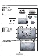
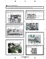
Remove the two screws. (BMZ30P080FTB)
1
Remove the two screws. (BPZ30P080FTB)
2
Remove the four screws. (AMZ30P060FTB)
3
Remove the side input shield.
4
Side Input Shield
2
Side input shield
Under cover (509)
SIDE IO Assy
SIDE HDMI Assy
SIDE KEY Assy
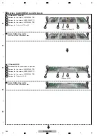
Screw tightening order
1
1
1
1
1
1
1
1
1
1
1
1
2
4
1
2
2
3
1
3
3
3
×
2
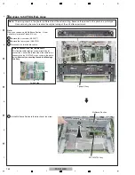
Remove the 10 screws. (ABA1377)
1
Remove the under cover (509).
2
Under Cover (509)
3
2
The other screws are random order.
Screw tightening order
The other screws are random order.
NEVER use an electric screwdriver
for tightening this screw.
Tighten it manually.
Summary of Contents for ARP3476
Page 10: ...10 PDP 5020FD 1 2 3 4 A B C D E F 1 2 3 4 2 2 SPECIFICATIONS ...
Page 11: ...11 PDP 5020FD 5 6 7 8 5 6 7 8 A B C D E F ...
Page 12: ...12 PDP 5020FD 1 2 3 4 A B C D E F 1 2 3 4 2 3 PANEL FACILITIES Front Section ...
Page 13: ...13 PDP 5020FD 5 6 7 8 5 6 7 8 A B C D E F Rear Section ...
Page 14: ...14 PDP 5020FD 1 2 3 4 A B C D E F 1 2 3 4 Remote Control Unit ...
Page 15: ...15 PDP 5020FD 5 6 7 8 5 6 7 8 A B C D E F ...
Page 21: ...21 PDP 5020FD 5 6 7 8 5 6 7 8 A B C D E F ...
Page 22: ...22 PDP 5020FD 1 2 3 4 A B C D E F 1 2 3 4 4 BLOCK DIAGRAM 4 1 OVERALL WIRING DIAGRAM 1 2 ...
Page 25: ...25 PDP 5020FD 5 6 7 8 5 6 7 8 A B C D E F OVERALL DIAGRAM PDP 5020FD ...
Page 31: ...31 PDP 5020FD 5 6 7 8 5 6 7 8 A B C D E F ...
Page 71: ...71 PDP 5020FD 5 6 7 8 5 6 7 8 A B C D E F ...
Page 192: ...192 PDP 5020FD 1 2 3 4 A B C D E F 1 2 3 4 9 6 PANEL CHASSIS SECTION ...


