


165
PDP-5020FD
5
6
7
8
5
6
7
8
A
B
C
D
E
F
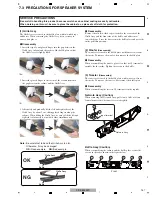
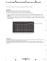
8.4 ADJUSTMENT WHEN THE SERVICE PANEL ASSY IS REPLACED
A
.
P
N E L
W
/
1
[
1
A
6 0 V S ]
F A C T
O
>
V
L
O F
T
F S E
< =
A
J
P
N E L – 1
A D
2
: 1
8
I
–
N 1
3
2
0 6 0
– R G B
H
J
–
B
1
5
10
15
16
1
5
10
15
20
25
30
32
1
2
3
4
5
6
7
8
9
A
B
C
D
E
After the panel is replaced with one for service, voltage margin adjustment is required.
Basically, voltage margin adjustment is performed using the Panel Factory menu.
After the panel is replaced and the unit is turned on, clear the pulse meter first.
For details on how to clear the pulse meter, see "8.3 HOW TO CLEAR HISTORY DATA".
∗
1: As various corrections are made referring to the pulse-meter count to calculate how long the panel has been used, if
adjustment of the panel for service is performed without clearing the pulse-meter count, proper adjustments will not be
performed.
∗
2: The drive sequence for Video 60-Hz is used for adjustment. When adjustment is made using the Panel Factory menu, the
current drive sequence is displayed on the screen, as shown in the figure below. Make sure that 60VS is always indicated
during
adjustment.
Example of the On-Screen display during Panel Factory mode
Drive sequence indication
[Preparation]
In the "PANEL-1ADJ" layer, the Panel White Balance value is reset to default, Panel Gamma is set to Straight, Noise is set to
OFF, LUT mode is set to ON and Reset active control is set to OFF.
If adjustment is performed using RS232C commands, unlike the case of Factory menu operation, adjustments are not
interlocked. Therefore, settings must be performed individually, by issuing commands. (See the section on preparations before
adjustment.)
[Supplement]
Summary of Contents for ARP3476
Page 10: ...10 PDP 5020FD 1 2 3 4 A B C D E F 1 2 3 4 2 2 SPECIFICATIONS ...
Page 11: ...11 PDP 5020FD 5 6 7 8 5 6 7 8 A B C D E F ...
Page 12: ...12 PDP 5020FD 1 2 3 4 A B C D E F 1 2 3 4 2 3 PANEL FACILITIES Front Section ...
Page 13: ...13 PDP 5020FD 5 6 7 8 5 6 7 8 A B C D E F Rear Section ...
Page 14: ...14 PDP 5020FD 1 2 3 4 A B C D E F 1 2 3 4 Remote Control Unit ...
Page 15: ...15 PDP 5020FD 5 6 7 8 5 6 7 8 A B C D E F ...
Page 21: ...21 PDP 5020FD 5 6 7 8 5 6 7 8 A B C D E F ...
Page 22: ...22 PDP 5020FD 1 2 3 4 A B C D E F 1 2 3 4 4 BLOCK DIAGRAM 4 1 OVERALL WIRING DIAGRAM 1 2 ...
Page 25: ...25 PDP 5020FD 5 6 7 8 5 6 7 8 A B C D E F OVERALL DIAGRAM PDP 5020FD ...
Page 31: ...31 PDP 5020FD 5 6 7 8 5 6 7 8 A B C D E F ...
Page 71: ...71 PDP 5020FD 5 6 7 8 5 6 7 8 A B C D E F ...
Page 192: ...192 PDP 5020FD 1 2 3 4 A B C D E F 1 2 3 4 9 6 PANEL CHASSIS SECTION ...