background image

Anschluss und Einstellung
• Stellen Sie mit Hilfe eines kleinen

Schraubendrehers den Ansprechwert ein.
Das Gerät hat eine Ansprechtoleranz von
± 15 %. Diese muss bei der Einstellung
berücksichtigt werden, falls ein nach
Norm geforderter Wert nicht unterschrit-
ten werden soll.
Ein beigefügter Aufkleber kann als
Verstellschutz gegen unbeabsichtigte
Veränderung der Einstellung dienen.

• Schließen Sie die Betriebserde an.
• Versorgungsspannung U

B

:

Für Betrieb mit 24 V AC/DC schließen
Sie die Versorgungsspannung zwischen
die Klemmen B3 und A2 an. Zwischen A1
und B3 darf keine Spannung anliegen.
Für Betrieb mit 42-240 V AC/DC schlie-
ßen Sie die Versorgungsspannung
zwischen die Klemmen A1 und A2 an.
Die Versorgungsspannung kann auch
dem Messkreis entnommen werden.

• Messkreis (zu überwachendes Netz)

- Zweiphasennetz: Schließen Sie jeweils

eine Phase des Spannungsnetzes an
die Klemmen B1 und B2 an.

- Dreiphasennetz: Brücken Sie Klemmen

B1 und B2 und schließen Sie sie an den
Sternpunkt des Spannungsnetzes an.

• Reset-Funktion

- Automatischer Reset: Bringen Sie den

Schiebeschalter MR/AR in Stellung AR
(Nicht speichern).

- Manueller Reset: Bringen Sie den

Schiebeschalter MR/AR in Stellung MR
(Speichern) oder brücken Sie Y1-Y2.

• Schließen Sie die Ausgangskontakte ent-

sprechend der Anwendungsschaltung an.

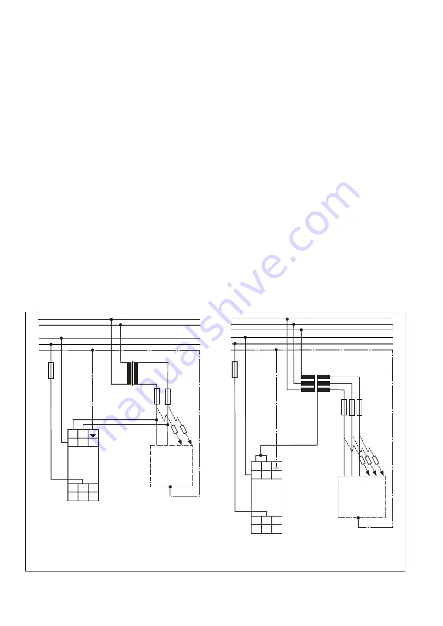
Fig. 3: Anwendungsschaltung AC

Application circuit AC
Schéma d’application AC

Fig. 4: Anwendungsschaltung 3 AC

Application circuit 3 AC
Schéma d’application 3 AC

T1

E1

N

U

N

U

E

R

E

R

1L1

1L2

PE

L1

N

B2

Y2

B3

A2

11

12

14

B1

Y1

A1

S1EN

B

U

F2

F1

T1

E1

F2

N

U

N

U

E

R

E

R

1L1

1L2

PE

L1
L2
L3

B2

Y2

B3

A2

11

12

14

B1

Y1

A1

S1EN

N

U

B

U

F1

Connection and setting
• Set the response value using a small

screwdriver.
The unit has a response tolerance of
± 15 %. This must be taken into
consideration when setting if a standard-
compliant value is not to be undershot.
An enclosed label can act as a guard
against an unintended change to the
setting.

• Connect the operating earth.
• Supply voltage U

B

:

To operate with 24 V AC/DC, connect the
supply voltage between the terminals B3
and A2. Voltage must not be applied
between A1 and B3.
To operate with 42 - 240 V AC/DC,
connect the supply voltage between
terminals A1 and A2.
The supply voltage also can be taken
from the measuring circuit.

• Measuring circuit (network to be moni-

tored)
- 2-phase network: connect one phase

of the monitored voltage to each of the
terminals B1 and B2.

- 3-phase network: link terminals B1 and

B2 and connect to the star point of the
voltage network.

• Reset function

- Automatic reset: set MR/AR sliding

switch to AR (do not store)

- Manual reset: set MR/AR sliding switch

to MR (store) or link Y1-Y2.

• Connect the output contacts according to

the application circuit.

Raccordement et réglage
• Réglez le seuil de déclenchement à l’aide

d’un petit tournevis.
L’appareil dispose d’une tolérance de
déclenchement de ± 15 %. Cela doit être
pris en compte lors du réglage dans le
cas où la valeur préconisée par la norme
ne doit pas être dépassée.
Un autocollant joint peut servir de
protection de réglage contre toute
modification involontaire du réglage.

• Reliez la borne de terre.
• Tension d’alimentation U

B

 :

Pour une alimentation en 24 V AC/DC,
reliez la tension d’alimentation entre les
bornes B3 et A2. Aucune tension ne doit
être appliquée entre les bornes A1et B3.
Pour une alimentation en 42-240 V
AC/DC
, reliez la tension d’alimentation
entre les bornes A1 et A2.
La tension d'alimentation peut aussi être
prélevée du circuit de mesure.

• Circuit de mesure (réseau à surveiller)

- circuit biphasé : reliez respectivement

une phase du réseau d’alimentation à
chaque borne B1 et B2.

- circuit triphasé : pontez les bornes B1

et B2 et reliez-les au point étoile du
réseau d’alimentation.

• Fonction de réarmement

- Réarmement automatique : commutez

le commutateur à glissière MR/AR sur
AR (pas de mémorisation).

- Réarmement manuel : commutez le

commutateur à glissière MR/AR sur
MR (mémorisation) ou pontez les
bornes Y1-Y2.

• Câblez les contacts de sortie suivant le

schéma d’application.

Summary of Contents for S1EN

Page 1: ... Application The S1EN insulation monitoring relay provides protection against insulation faults in galvanically isolated voltage supplies IT supplies It meets the requirements of DIN EN 61557 8 The S1EN is designed for use as an insulation monitor trip device if insulation resistances are outside the permitted range The S1EN is designed for use in industrial environments only It is not suitable fo...

Page 2: ...uit Function description The insulation monitoring relay prevents of hazardous insulation faults in galvanically separated supply networks The insulation resistance is measured between the network phases and the operating earth If the response value Ran resistance is reached the unit is triggered As long as the response value in both measuring circuits is less than the insula tion resistance RE Ra...

Page 3: ...not store connect the external reset button at terminals Y1 Y2 Function testing By setting the integrated test switch to TP the unit can be tested for the correct trip operation Installation The unit must be cabinet mounted min of IP 54 There is a notch on the rear of the unit for DIN rail attachment Commissioning Please note for commissioning The output contact 11 12 14 is an auxiliary contact e ...

Page 4: ...intended change to the setting Connect the operating earth Supply voltage UB To operate with 24 V AC DC connect the supply voltage between the terminals B3 and A2 Voltage must not be applied between A1 and B3 To operate with 42 240 V AC DC connect the supply voltage between terminals A1 and A2 The supply voltage also can be taken from the measuring circuit Measuring circuit network to be moni tore...

Page 5: ...and 11 12 open If an insulation fault occurs the contact 11 14 opens and 11 12 closes The Fault LED is illuminated Application The following circuit examples are typical applications of the S1EN An insulation fault on a connected user triggers the S1EN and a fault message occurs Testing Fault causes By short circuiting the measuring circuits you can simulate an earth fault to verify that the unit ...

Page 6: ... de commutation pour CL 1 µF Max Ansprechfehler nach Max response error to Décalage max du point de déclenchement selon DIN EN 61557 8 05 98 Messzeit Measuring time Temps de mesure Grenzbelastbarkeit Loading capacity limit Caractéristiques de commutation Max zulässiger Einschaltstrom Max permitted inrush current Courant d enclenchement max admissible Prüfspannung nach Test voltage to Tension de co...

Page 7: ...ndhülsen Max cable cross section single core or multicore with crimp connectors Max raccordement conducteur unique ou multiple avec embout Anzugsdrehmoment für Anschlussklemmen Schrauben Torque setting for connection terminal screws Couple de serrage des bornes de raccordement vis Schutzarten Protection Indice de protection Einbauraum z B Schaltschrank Mounting e g cabinet Lieu d implantation p ex...

Page 8: ... Fax 021 4804994 E Mail sales pilz ie J Pilz Japan Co Ltd 045 471 2281 Fax 045 471 2283 E Mail pilz pilz co jp MEX Pilz de Mexico S de R L de C V 55 5572 1300 Fax 55 5572 4194 E Mail info mx pilz com NL Pilz Nederland 0347 320477 Fax 0347 320485 E Mail info pilz nl NZ Pilz New Zealand 09 6345 350 Fax 09 6345 352 E Mail t catterson pilz co nz P Pilz Industrieelektronik S L 229407594 Fax 229407595 E...

Page 9: ... deve essere montato in un armadio elettrico con un tipo di protezio ne corrispondente al grado IP 54 per evitare che polvere e umidità possano pregiudicarne il funzionamento Assicurare un adeguata protezione su tutti i contatti di uscita per i carichi capacitivi e induttivi La presente descrizione funge da manuale di istruzioni e va conservata in previsione di un futuro impiego Uso previsto Il re...

Page 10: ... reti a tensione continua e alternata Collegamento per contatti esterni per l attivazione della funzione di reset Il dispositivo S1EN risponde ai seguenti requisiti di sicurezza Garantisce la protezione dell impianto sottoposto a controllo nel caso di Caduta di tensione Difetto della bobina Interruzione di un conduttore Cortocircuito del circuito di misurazione Descrizione del funzionamento Il rel...

Page 11: ... è aumentata fino al valore di reset RE Rab Reset manuale MR Non appena la resistenza di isolamento è aumentata fino a raggiungere il valore di reset RE Rab ci sono due possibilità per riattivare il S1EN Portando brevemente l interruttore MR AR in posizione AR non salvare Collegando il tasto di reset esterno ai morsetti Y1 e Y2 Verifica di funzionamento Portando l interruttore di verifica integrat...

Page 12: ... dispersione a terra resistenza vera Connessione e regolazione Con l ausilio di un piccolo cacciavite regolare il valore di risposta La tolleranza di risposta del dispositivo è di 15 Questo valore deve essere tenuto in considerazione in fase di regolazione nel caso in cui il valore di risposta debba rimanere al di sotto di un valore previsto per norma Un etichetta adesiva può proteggere da un even...

Page 13: ... het contact 11 12 is geopend Bij isolatiefouten gaat contact 11 14 open contact 11 12 sluit De LED voor storing licht op Toepassing De schakelingen fig 3 t m fig 6 zijn typische toepassingen van de S1EN Als er op een aangesloten verbruiker een isolatiefout optreedt geeft de S1EN een storingsmelding Comprobación causas de errores Mediante el puenteado de los circuitos de medición se puede simular ...

Page 14: ...elpuntverschuiving bij CL 1 µF Máx error de respuesta según Errore di risposta max conformemente alla norma Max aanspreekfout volgens DIN EN 61557 8 05 98 Tiempo de medición Intervallo di misurazione Meettijd Capacidad de carga límite Sollecitazione limite Grensbelastbaarheid Corriente de conexión máxima permitida Corrente d inserimento max consentita Max toegelaten inschakelstroom Tensión de prue...

Page 15: ...re unico o multiplo con capicorda Max aansluitdoorsnede enkele of meerdere draden met adereindhulzen Par de apriete para bornes de conexión tornillos Coppia di serraggio per i morsetti viti Aanhaalmoment voor aansluitklemmen schroeven Grados de protección Tipi di protezione Beschermingsgraad Lugar de montaje p ej armario de distribución Spazio di montaggio p es quadro elettrico ad armadio Inbouwru...

Page 16: ... Fax 021 4804994 E Mail sales pilz ie J Pilz Japan Co Ltd 045 471 2281 Fax 045 471 2283 E Mail pilz pilz co jp MEX Pilz de Mexico S de R L de C V 55 5572 1300 Fax 55 5572 4194 E Mail info mx pilz com NL Pilz Nederland 0347 320477 Fax 0347 320485 E Mail info pilz nl NZ Pilz New Zealand 09 6345 350 Fax 09 6345 352 E Mail t catterson pilz co nz P Pilz Industrieelektronik S L 229407594 Fax 229407595 E...

Reviews: