background image

Overview

Operating Manual PSSu E F 2DOR 8(-T)(-R)
21334-EN-13

| 7

2

Overview

2.1

Module structure

A module consists of

}

Electronic module and

}

Base module with

– Screw terminals or
– Cage clamp terminals

The base modules are the carrier units for the electronic modules and are used to connect
the field wiring. The electronic modules are inserted on to the base modules and determine
the module's function.
Details of the base modules that can be used are available in the chapter entitled “Intended
Use”.

2.2

Module features

The product has the following features:

}

Relay contacts

– N/O contact
– Volt-free
– Current load capacity per output: 8 A

}

LEDs for:

– Switch status of each output
– Module error

Summary of Contents for PSSu E F 2DOR 8

Page 1: ...PSSu E F 2DOR 8 T R Operating Manual 21334 EN 13 Decentralised system PSSuniversal I O ...

Page 2: ...enta tion will be gratefully received Source code from third party manufacturers or open source software has been used for some components The relevant licence information is available on the Internet on the Pilz homepage Pilz PIT PMI PNOZ Primo PSEN PSS PVIS SafetyBUS p SafetyEYE SafetyNET p the spirit of safety are registered and protected trademarks of Pilz GmbH Co KG in some countries SD means...

Page 3: ...tion mechanisms 15 4 2 3 Reaction times 15 4 3 Configuration 15 4 3 1 PSSu assignment in system environment A 15 4 3 1 1 Addresses in the process image 16 4 3 2 PSSu assignment in system environment B 16 5 Installation 17 5 1 General installation guidelines 17 5 1 1 Dimensions 17 5 2 Installing the base module 18 5 3 Inserting and removing an electronic module 19 5 3 1 Inserting an electronic modu...

Page 4: ...ay elements for module diagnostics 29 7 2 2 Display elements for an output s FS enable 29 7 2 3 Display elements for output status 30 8 Technical details 31 8 1 Safety characteristic data 35 8 2 Service life graphs 36 9 Order reference 38 9 1 Product 38 9 2 Accessories 38 ...

Page 5: ...should be retained for future reference 1 1 2 Terminology System environment A and B The PSSu system can be used in two different system environments The module s applic ation area is described in the chapter Intended Use of the manual The distinction is made between PSSu in system environment A PSSu in system environment B The distinction is based on the application area of the PSSu system PSSu i...

Page 6: ...situation that could lead to serious injury and death and indicates preventive measures that can be taken CAUTION This refers to a hazard that can lead to a less serious or minor injury plus material damage and also provides information on preventive measures that can be taken NOTICE This describes a situation in which the product or devices could be dam aged and also provides information on preve...

Page 7: ...he electronic modules and are used to connect the field wiring The electronic modules are inserted on to the base modules and determine the module s function Details of the base modules that can be used are available in the chapter entitled Intended Use 2 2 Module features The product has the following features Relay contacts N O contact Volt free Current load capacity per output 8 A LEDs for Swit...

Page 8: ... 2 3 Front view 21 11 22 12 24 14 41 31 42 32 44 34 Err 11 O0 21 12 O0 22 O0 13 C 23 C 14 24 PSSu E F 2DOR 8 31 O1 41 32 O1 42 O1 33 C 43 C 34 44 11 31 FS0 FS1 23 13 43 33 PSSu E F 2DOR 8 312225 000000 001 10 1 3 4 9 8 5 6 7 11 2 12 A B Legend A Electronic module B Base module 1 LEDs for Module diagnostics Displaying an output s FS enable enable principle 2 Labelling strip with Name of electronic ...

Page 9: ...Connection level 3 9 Connection level 4 10 Square mounting holes connection levels 1 2 3 and 4 With screw to loosen tighten the screw terminal on base modules with screw termin als With mechanism to operate the cage clamp on base modules with cage clamp termin als 11 Round connection holes connection levels 1 2 3 and 4 for connecting the signal lines 12 Mounting slot for colour marker to label the...

Page 10: ... the furnace is used in continuous operation appropriate external measures must be used to establish diversity of the shutdown elements requirement of EN 50156 1 For example an appropriate measure may be an additional monitored switching element contactor or relay which is controlled by a safe semiconductor output and is switched in series with both relay outputs The module PSSu E F 2DOR 8 T is su...

Page 11: ... personnel The products may only be assembled installed programmed commissioned operated maintained and decommissioned by competent persons A competent person is a qualified and knowledgeable person who because of their train ing experience and current professional activity has the specialist knowledge required To be able to inspect assess and operate devices systems and machines the person has to...

Page 12: ...g followed the guidelines in the manual Operating personnel are not suitably qualified Any type of modification has been made e g exchanging components on the PCB boards soldering work etc 3 2 3 Disposal In safety related applications please comply with the mission time TM in the safety related characteristic data When decommissioning please comply with local regulations regarding the disposal of ...

Page 13: ...4 Function description 4 1 Block diagram K0 K1 14 24 C Rail Module Bus Periphery Supply 24 V DC Module Supply 5 V DC Data FS 34 44 21 41 12 32 22 42 11 31 13 23 33 43 4 2 Module features 4 2 1 Functions Module supply The module supply provides the module with voltage Outputs ...

Page 14: ...illustrated in the following derating diagram The operating point should be below the characteristic curve PSSu E F 2DOR 8 Derating diagram for the permitted ambient temperature T dependent on load current I 20 40 60 80 100 0 1 2 3 4 5 6 7 8 9 10 I A T C PSSu E F 2DOR 8 T R Derating diagram for the permitted ambient temperature T de pendent on load current I 20 40 60 80 100 0 1 2 3 4 5 6 7 8 9 10 ...

Page 15: ...rature monitoring The module provides the following diagnostic data Start up error Configuration error FS communication error Bus termination error Temperature error Too warm Temperature error Too hot Relay control error Relay error 4 2 3 Reaction times Information on the reaction times of the outputs can be found in the PSSuniversal System Description 4 3 Configuration 4 3 1 PSSu assignment in sy...

Page 16: ... Configurator s online help 4 3 1 1 Addresses in the process image The module occupies 2 consecutive bit addresses in the process image The process im age in which the outputs are shown depends on the configuration With write access the Bits in the ST PIO are used to switch the FS outputs with the local enable principle Configuration SafetyBUS p Standard bus system FS PIO ST PII ST PIO None 2 Bit ...

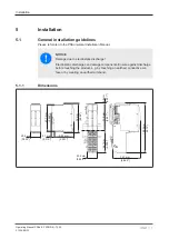
Page 17: ...amage due to electrostatic discharge Electrostatic discharge can damage components Ensure against discharge before touching the product e g by touching an earthed conductive sur face or by wearing an earthed armband 5 1 1 Dimensions 25 2 mm 76 mm 52 1 mm 8 1 mm 67 7 mm 25 2 mm 56 1 mm 71 8 mm 0 8 mm 128 9 mm 72 7 mm 2 862 2 992 2 209 2 827 0 031 5 075 0 992 2 051 0 319 0 992 2 665 ...

Page 18: ...d base modules with cage clamp terminals All contacts should be protected from contamination The mechanics of the base modules are designed for 50 plug in out cycles Procedure We recommend that you wire up the base modules before inserting the electronic mod ules Slot the groove on the base module on to the mounting rail from below 1 Push the base module back 2 until you hear it lock into position...

Page 19: ...s may only be inserted and removed when the load is switched off Unforeseeable error reactions may be triggered if modules are inserted and removed under load When an electronic module is plugged into a base module for the first time one part of the coding element remains on the electronic module while its counterpart is fixed on to the base module This is how the base module is coded The mechanic...

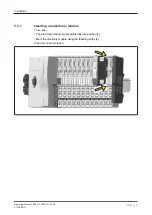
Page 20: ...ual PSSu E F 2DOR 8 T R 21334 EN 13 20 5 3 1 Inserting an electronic module Procedure The electronic module must audibly lock into position 1 Mark the electronic module using the labelling strips 2 Schematic representation 2 1 1 ...

Page 21: ...ring operation The configuration data is re tained when a module is changed Effects System environment A In the event of a potential FS communication error the FS section of the PSSu sys tem and all relevant I O Groups SafetyBUS p switch to a STOP condition System environment B All FS hardware outputs on the PSSu system switch to a safe condition The substitute values are used for the modules FS o...

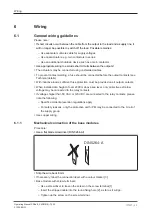
Page 22: ...ufficient fuse protection must be provided on all output contacts When installed at a height of over 2000 m above sea level only protective extra low voltage may be connected to the relay contacts If voltages higher than 50 VAC or 120 VDC are connected to the relay contacts please note the following Specific accident prevention regulations apply For safety reasons only the protective earth PE may ...

Page 23: ... the cable is firmly seated 21 11 1 3 2 4 5 6 Please note The minimum cable cross section for field connection terminals on the base modules is 0 14 mm2 AWG26 The maximum cable cross section for field connection terminals is Digital inputs 1 5 mm2 AWG16 Digital outputs 2 0 mm2 AWG14 Inputs outputs on the counter modules 1 5 mm2 AWG16 Analogue inputs outputs 1 5 mm2 AWG16 Communication cables 1 5 m...

Page 24: ...o EN 60947 1 such as the PZ 1 5 or PZ 6 5 from Weidmüller for example Maximum torque setting 0 8 Nm Use copper wiring 6 2 Terminal configuration Base module Terminal configuration With C rail 11 Output O0 Relay contact 1 21 Not assigned 12 22 Output O0 Relay contact 2 12 22 linked within the base module 13 23 C rail supply 13 23 33 43 linked within the base module 14 24 Not assigned 31 Output O1 R...

Page 25: ...11 Output O0 Relay contact 1 21 Not assigned 12 22 Output O0 Relay contact 2 12 22 linked within the base module 14 24 Not assigned 31 Output O1 Relay contact 1 41 Not assigned 32 42 Output O1 Relay contact 2 32 42 linked within the base module 34 44 Not assigned 21 11 22 12 23 13 24 14 41 31 42 32 43 33 44 34 ...

Page 26: ... the module Output circuit With C rail Single channel actuator Switches 230 VAC 21 11 22 12 23 13 24 14 O0 O0 n c O1 n c O1 C 41 31 42 32 43 33 44 34 L1 C N Dual channel actuator Switches 230 VAC 21 11 22 12 23 13 24 14 O0 O0 n c O1 n c O1 C 41 31 42 32 43 33 44 34 L1 C N M ...

Page 27: ...commissioning An error must be simulated for each safety related output during commissioning The anti cipated error reaction must occur when an output has a short circuit to a supply voltage INFORMATION The short circuit test must be performed on the load and not on the output terminal ...

Page 28: ...s signalled to the head module and then entered in the Error stack with PSSu in system environment A Diagnostic log with PSSu in system environment B of the head module The module can detect the following errors Module error Explanation Remedy Start up error Error as the PSSu system starts up Change faulty module Configuration error Incorrect module type configured The configured hardware registry...

Page 29: ...odule If the temperature drops back below the threshold value the module sends an all clear Too hot If a module s temperature exceeds a further threshold value the module sends an error message to the head module and triggers an I O Group stop 7 2 Display elements Legend LED on LED off 7 2 1 Display elements for module diagnostics The module has an LED for displaying module errors Err LED Err 11 I...

Page 30: ...e for output O1 Yellow FS enable for output O1 7 2 3 Display elements for output status Each output is assigned an LED for displaying the output status LEDs 11 and 31 Err 11 O0 21 12 O0 22 O0 13 C 23 C 14 24 31 O1 41 32 O1 42 O1 33 C 43 C 34 44 11 31 11 31 LED Meaning Designa tion Colour Status Signal Output Terminal 11 0 signal O0 Out put 1 11 12 22 Green 1 signal 31 0 signal O1 Out put 2 31 32 4...

Page 31: ...om FS firmware ver sion head modules 1 0 0 1 0 0 1 5 0 Electrical data 312225 314225 315225 Internal supply voltage module supply Module s power con sumption 0 2 W 0 2 W 0 2 W Periphery s supply voltage periphery supply Voltage range 16 8 30 V 16 8 30 V 16 8 30 V Module s current con sumption with no load 60 mA 60 mA 60 mA Module s power con sumption with no load 1 5 W 1 5 W 1 5 W Max power dissip...

Page 32: ... 100 W Utilisation category In accordance with the standard EN 60947 5 1 EN 60947 5 1 EN 60947 5 1 Utilisation category of safety contacts AC15 at 230 V 230 V 230 V Max current 3 A 3 A 3 A AC15 with condensa tion at 30 V 30 V Max current 3 A 3 A DC13 6 cycles min at 24 V 24 V 24 V Max current 5 A 5 A 5 A DC13 at 60 V Max current 0 7 A Utilisation category in ac cordance with UL Voltage 250 V AC G ...

Page 33: ...lay contact 1 and relay contact 2 4900 V prot separation 4900 V prot separation 4900 V prot separation Environmental data 312225 314225 315225 Application site In accordance with the standard EN 50125 3 Application site Track area 1 m 3 m In accordance with the standard EN 61373 Application site Category 1 Class A B Climatic suitability EN 60068 2 1 EN 60068 2 14 EN 60068 2 2 EN 60068 2 30 EN 6006...

Page 34: ... EN 61000 6 4 EN 61000 4 2 EN 61000 4 3 EN 61000 4 4 EN 61000 4 5 EN 61000 4 6 EN 61000 6 2 EN 61000 6 4 Vibration In accordance with the standard EN 60068 2 6 EN 60068 2 6 EN 50125 3 Frequency 10 150 Hz 10 150 Hz 5 2000 Hz Acceleration 1g 1g 0 23g Broadband noise In accordance with the standard EN 60068 2 64 EN 61373 Frequency 5 500 Hz 5 150 Hz Acceleration 1 9grms 0 79 g RMS Shock stress In acco...

Page 35: ... 2 mm Weight 90 g 91 g 93 g Mechanical coding Type H H H Colour Yellow Yellow Yellow Where standards are undated the 2009 10 latest editions shall apply Further information about the switching capability is available in the service life graphs 8 1 Safety characteristic data NOTICE You must comply with the safety characteristic data in order to achieve the required safety level for your plant machi...

Page 36: ...service life graphs are met The PFH value depends on the switch frequency and the load of the relay output If the service life graphs are not accessible the stated PFH value can be used irrespective of the switch frequency and the load as the PFH value already considers the relay s B10d value as well as the failure rates of the other components 8 2 Service life graphs The service life graphs indic...

Page 37: ...00 cycles Provided the application to be implemented requires fewer than 1 000 000 cycles the PFH value see Technical details 31 can be used in the calculation To increase the service life sufficient spark suppression must be provided on all relay con tacts With capacitive loads any power surges that occur must be noted With DC contact ors use flywheel diodes for spark suppression We recommend you...

Page 38: ...C rail with screw terminals 312 628 PSSu BP 2 16 S T Base module without C rail with screw terminals T type 314 628 PSSu BP 2 16 C Base module without C rail with cage clamp terminals 312 629 PSSu BP 2 16 C T Base module without C rail with cage clamp terminals T type 314 629 PSSu BP C 2 16 S Base module with C rail and screw terminals 312 630 PSSu BP C 2 16 S T Base module with C rail and screw t...

Page 39: ...fetyNET p THE SPIRIT OF SAFETY are registered and protected trademarks of Pilz GmbH Co KG in some countries We would point out that product features may vary from the details stated in this document depending on the status at the time of publication and the scope of the equipment We accept no responsibility for the validity accuracy and entirety of the text and graphics presented in this informati...

Reviews: