


- 4 -
• With AC operating voltage a detachable
connection is required between unit and
system earth. With DC operating voltage
this connection is not necessary.
To operate:
• Supply operating voltage
- AC: Connect the operating voltage to
terminals A1 and A2; connect the
operating earth terminal with the
ground earth.
- DC: Connect the terminals B1 and B2
with the operating voltage.
• Feedback control loop:
Bridge Y1 - Y2 or connect external n/c
contacts in series from other devices .
• Reset circuit:
- Automatic reset: Bridge S33-S34
- Manual reset: Connect button to S33-
S34
- Manual reset with monitoring: Connect
button to S33-S34, bridge S34-S37.
• Input circuit:
- Single-channel: Bridge S21-S22 and
S31-S32. Connect N/C contact from
safety switch (e.g. Emergency-Stop) to
S12 and S11.
- Two-channel: Bridge S11-S12. Connect
N/C contact from safety switch (e.g.
Emergency-Stop) to S21-S22 and S31-
S32.
• 24 VDC supply voltage for semi-
conductor output: C24 VDC to
terminals Y31 and 0 VDC to Y30.
The safety contacts are activated (closed)
and the auxiliary contact (81 - 82) is open.
The status indicators "CH.1", "CH.2",
"CH.1 IN" and "CH.2 IN" are illuminated.
The unit is ready for operation. If the input
circuit is opened, the safety contacts 13-14/
23-24 ... 73-74 open and the auxiliary
contact 81-82 closes. The status indicator
goes out.
Reactivation
• Close the input circuit.
• For manual reset without monitoring,
momentary closure of the button between
S33 and S34 must be pressed; for
manual reset with monitoring, press the
button and release again.
The status indicators light up again, the
safety contacts are closed.
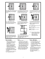
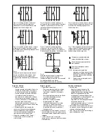
Application
• Fig.2...Fig.9 show connection examples
for Emergency Stop wiring with manual
and monitored reset. Safety gate controls
as well as contact expansion via external
contactors.
• Fig. 8: Simultaneity 120 ms
• Pour les tensions d'alimentation alternati-
ves UB~, une liaison amovible entre le
boîtier et la terre est exigée. Cette liaison
n'est pas nécessaire pour les relais
alimentés en 24 V DC.
Mise en oeuvre:
• Tension d’alimentation
- AC: amener la tension d’alimentation
sur A1 et A2; relier la borne terre
- DC: amener la tension d’alimentation
sur B1 et B2
• Boucle de retour:
Pontage de Y1-Y2 ou branchement des
contacts externes
• Circuit de réarmement:
- Réarmement automatique: pontage des
bornes S33-S34
- Réarmement manuel: câblage d’un
poussoir sur S33-S34
- Surveillance du circuit de réarmement:
câblage d'un poussoir sur S33-S34 et
pontage des bornes S34-S37.
• Circuits d’entrée:
- Commande par 1 canal: câblage du
contact à ouverture entre S11-S12,
pontage entre S21-S22 et S31-S32
- Commande par 2 canaux: câblage des
contacts à ouverture entre S21-S22 et
S31-S32, pontage entre S11-S12
• Alimentation en 24 VCC des sorties
statiques: relier le +24 V DC à la borne
Y31 et le 0 V à la borne Y30.
Les contacts de sécurité se ferment et le
contact d’information 81-82 s’ouvre. Les
LEDs "CH.1", "CH.2", "CH.1 IN" and
"CH.2 IN" sont allumées. L’appareil est prêt
à fonctionner.
Si le circuit d’entrée est ouvert, les contacts
de sécurité retombent et le contact
d’information 81-82 se ferme. Les LEDs
s’éteignent.
Remise en route:
• fermer le circuit d’entrée
• en cas de réarmement manuel sans
surveillance, appuyer sur le poussoir de
validation entre S33-S34. En cas de
surveillance du circuit de réarmement,
appuyer puis relacher le poussoir de
validation.
Les affichages d'état s'allument à nouveau.
Les contacts de sécurité sont fermées.
Utilisation
• Dans les figures 2 à 9 sont représentés
les différents cablages possibles du
PNOZ 11: poussoirs AU avec surveillance
du circuit de réarmement, interrupteurs
de position et augmentation du nombre
des contacts par contacteurs externes.
• Fig. 8: Désynchronisme: 120 ms
• Bei Betrieb mit Wechselspannung ist
eine lösbare Verbindung zwischen Gerät
und Betriebserde erforderlich. Der
Anschluss entfällt bei Gleichspannung.
Ablauf:
• Versorgungsspannung:
- AC: Versorgungsspannung an Klem-
men A1 und A2 anlegen; Betriebser-
dungsklemme mit Schutzleitersystem
verbinden.
- DC: Versorgungsspannung an Klem-
men B1 und B2 anlegen
• Rückführkreis:
Brücke an Y1-Y2 oder externe Schütze
anschließen.
• Startkreis:
- Automatischer Start: S33-S34 brücken.
- Manueller Start: Taster an S33-S34
anschließen.
- Manueller Start mit Überwachung:
Taster an S33-S34 anschließen, S34-
S37 brücken.
• Eingangskreis:
- Einkanalig: S21-S22 und S31-S32
brücken. Öffnerkontakt von Auslöse-
element an S12 und S11 anschließen.
- Zweikanalig: S11-S12 brücken.
Öffnerkontakt von Auslöseelement an
S21-S22 und S31-S32 anschließen.
• 24 V Versorgungsspannung für
Halbleiterausgänge: +24 V DC an
Klemme Y31 und 0 V an Klemme Y30
anschließen.
Die Sicherheitskontakte sind aktiviert
(geschlossen) und der Hilfskontakt (81-82)
ist geöffnet. Die Statusanzeige für "CH.1",
"CH. 2", CH.1 IN" und "CH. 2 IN" leuchten.
Das Gerät ist betriebsbereit.
Wird der Eingangskreis geöffnet, öffnen die
Sicherheitskontakte 13-14/23-24 ... 73-74
und der Hilfskontakt 81-82 schließt. Die
Statusanzeige erlischt.
Wieder aktivieren
• Eingangskreis schließen.
• Bei manuellem Start ohne Überwachung
zusätzlich Taster zwischen S33 und S34
betätigen, bei manuellem Start mit
Überwachung Taster betätigen und
wieder loslassen.
Die Statusanzeigen leuchten wieder, die
Sicherheitskontakte sind geschlossen.
Anwendung
• In Fig. 2 ... Fig. 9 sind Anschlussbeispiele
für Not-Halt-Beschaltung mit manuellem
und überwachtem Start, Schutztüran-
steuerungen sowie Kontaktvervielfachung
durch externe Schütze dargestellt.
• Fig. 8: Gleichzeitigkeit: 120 ms


