


- 3 -
• Manueller Start: Gerät ist erst dann aktiv,
wenn ein Starttaster betätigt wird.
• Manueller Start mit Überwachung: Gerät
ist erst aktiv, wenn der Starttaster betätigt
und wieder losgelassen wurde.
• Kontaktvervielfachung und -verstärkung
durch Anschluss von externen Schützen
Gleichzeitigkeit
Bei zweikanaligem Betrieb darf die Zeit
zwischen dem Schließen der beiden Not-
Halt-Kontakte unendlich betragen.
• Réarmement manuel: le relais n’est activé
qu’après une impulsion sur un poussoir
de validation.
• Surveillance de circuit de réarmement: le
relais n'est activé qu'après le relachement
du poussoir de validation.
• Augmentation du nombre de contacts ou
du pouvoir de coupure par l’utilisation de
contacteurs externes.
Désynchronisme
En cas de commande par 2 canaux avec
des poussoirs AU, le désynchronisme entre
les 2 canaux peut être infini.
Montage
Le relais doit être monté en armoire ayant
un indice de protection mini IP54. Sa face
arrière permet un montage sur rail DIN.
Immobilisez l'appareil monté sur un rail DIN
vertical (35 mm) à l'aide d'un élément de
maintien comme par ex. un support ou une
équerre terminale.
• Manual reset: Unit is only active when a
reset button has been pressed.
• Manual reset with monitoring: Unit is only
activated, when the reset button ist
pressed and then released.
• Increase in the number of available
contacts by connection of external
contactors/relays.
Simultaneity
By dual channelled operation the time
between the closing of both Emergency
Stop buttons can be infinity.
Montage
Das Sicherheitsschaltgerät muss in einen
Schaltschrank mit einer Schutzart von mind.
IP54 eingebaut werden. Zur Befestigung auf
einer Normschiene dient ein Rastelement
auf der Rückseite des Geräts.
Sichern Sie das Gerät bei Montage auf
einer senkrechten Tragschiene (35 mm)
durch ein Halteelement wie z. B. Endhalter
oder Endwinkel.
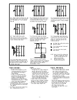
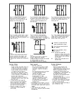
Inbetriebnahme
Beachten Sie bei der Inbetriebnahme:
• Auslieferungszustand: Brücke zwischen
S11-S12 (Eingangskreis zweikanalig) und
Brücke zwischen Y1-Y2 (Rückführkreis)
• Nur die Ausgangskontakte 13-14/23-24 ...
73-74 sind Sicherheitskontakte. Aus-
gangskontakt 81-82 ist ein Hilfskontakt
(z. B. für Anzeige).
• Vor die Ausgangskontakte eine Sicherung
(siehe techn. Daten) schalten, um das
Verschweißen der Kontakte zu verhindern.
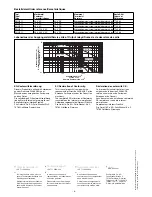
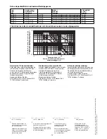
• Berechnung der max. Leitungslänge I
max
im Eingangskreis:
R
lmax
R
l
/ km
I
max
=
R
lmax
= max. Gesamtleitungswiderstand
(s. technische Daten)
R
l
/km = Leitungswiderstand/km
Da die Funktion Querschlusserkennung
nicht einfehlersicher ist, wird sie von Pilz
während der Endkontrolle geprüft. Eine
Überprüfung nach der Installation des
Geräts ist wie folgt möglich:
1. Gerät betriebsbereit (Ausgangs-
kontakte geschlossen)
2. Die Testklemmen S12-S22 zur
Querschlussprüfung kurzschließen.
3. Die Sicherung im Gerät muss auslösen
und die Ausgangskontakte öffnen.
Leitungslängen in der Größenordnung
der Maximallänge können das Auslö-
sen der Sicherung um bis zu 2 Minuten
verzögern.
4. Sicherung wieder zurücksetzen: den
Kurzschluss entfernen und die
Versorgungsspannung für ca. 1 Minute
abschalten.
• Leitungsmaterial aus Kupferdraht mit
einer Temperaturbeständigkeit von
60/75 °C verwenden.
• Sorgen Sie beim Anschluss von magne-
tisch wirkenden, auf Reedkontakten
basierenden Näherungsschaltern dafür,
dass der max. Einschaltspitzenstrom (am
Eingangskreis) den Näherungsschalter
nicht überlastet.
• Angaben im Kapitel „Technische Daten“
unbedingt einhalten.
Installation
The safety relay must be panel mounted
(min. IP54). There is a notch on the rear of
the unit for DIN-Rail attachment.
If the unit is installed on a vertical mounting
rail (35 mm), ensure it is secured using a
fixing bracket such as end bracket.
Operation
Please note for operation:
• Unit delivered with a bridge between S11-
S12 (2-channel input circuit) and a bridge
between Y1-Y2 (Feedback Control Loop)
• Only the output contacts 13-14/23-24 ...
73-74 are safety contacts. Output contact
81-82 is an auxiliary contact (e.g. for a
display).
• To prevent a welding together of the
contacts, a fuse (see technical data)
must be connected before the output
contacts.
• Calculate the max. Cable runs I
max
in the
input circuit:
R
lmax
R
l
/ km
I
max
=
R
lmax
= Max. Total cable resistance (see
technical details)
R
l
/km = Cable resistance/km
As the function for detecting shorts across
the inputs is not failsafe, it is tested by
Pilz during the final control check.
However, a test is possible after installing
the unit and it can be carried out as
follows:
1. Unit ready for operation (output
contacts closed)
2. Short circuit the test (connection)
terminals S12-S22 for detecting shorts
across the inputs
3. The unit‘s fuse must be triggered and
the output contacts must open. Cable
lengths in the scale of the maximum
length can delay the fuse triggering for
up to 2 minutes.
4. Reset the fuse: remove the short circuit
and switch off the operating voltage for
approx. 1 minute.
• Use copper wiring that will withstand
60/75 °C
• When connecting magnetically operated,
reed proximity switches, ensure that the
max. peak inrush current (on the input
circuit) does not overload the proximity
switch.
• Important details in the section "Technical
Data“ should be noted and adhered to.
Mise en oeuvre
Remarques préliminaires:
• Pontages présents à la livraison: S11-S12
(commande par 2 canaux) et Y1-Y2
(boucle de retour)
• Seuls les contacts 13-14,23-24 ... 73-74
sont des contacts de sécurité. Le contact
81-82 est un contact d’information (ex.
voyant)
• Protection de contacts de sortie par
des fusibles (voir caractéristiques
techniques) pour éviter leur soudage
• Calcular les longueurs de câblage max
I
max
dans le circuit d’entrée:
R
lmax
R
l
/ km
I
max
=
R
lmax
= résistivité de câblage totale max.
(voir les caractéristiques techniques)
R
l
/km = résistivité de câblage/km
La fonction de détection de court-circuit
est testé par Pilz lors du contrôle final. Un
test sur site est possible de la façon
suivante:
1. Appareil en fonction (contacts de sortie
fermés)
2. Court-circuiter les bornes de
raccordement nécessaires au test S12-
S22
3. Le fusible interne du relais doit
déclencher et les contacts de sortie
doivent s‘ouvrir. Le temps de réponse
du fuisible peut aller jusqu‘à 2 min. si
les longueurs de câblage sont proches
des valeurs maximales.
4. Réarmement du fusible: enlever le
court-circuit et couper l‘alimentation du
relais pendant au moins 1 min.
• Utiliser uniquement des fils de cablâge en
cuivre 60/75 °C.
• Lors du raccordement de détecteurs de
proximité magnétiques, basés sur des
contacts Reed, veuillez vous assurer que
le courant de crête max. à la mise sous
tension (sur le circuit d'entrée) ne
surcharge pas les détecteurs de
proximité.
• Respecter les données indiquées dans le
chap. „Caractéristiques techniques“.


