

- 3 -
• Kontaktvervielfachung und -verstärkung
durch Anschluss von externen Schützen
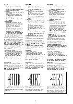
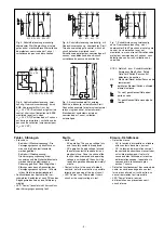
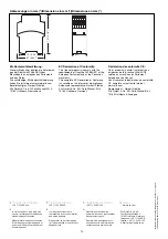
Montage
Bauen Sie das Sicherheitsschaltgerät in
einen Schaltschrank mit einer Schutzart von
mindestens IP54 ein. Zur Befestigung auf
einer Normschiene dient das Rastelement
auf der Rückseite des Geräts.
Sichern Sie das Gerät bei Montage auf einer
senkrechten Tragschiene (35 mm) durch ein
Halteelement wie z. B. Endhalter oder
Endwinkel.
Inbetriebnahme
Beachten Sie bei der Inbetriebnahme:
• Gerät nur im spannungslosen Zustand
verdrahten!
• Das Netzteil muss den Vorschriften für
Funktionskleinspannungen mit sicherer
elektrischer Trennung (SELV, PELV)
nach VDE 0100, Teil 410 entsprechen.
• Leitungsmaterial aus Kupferdraht mit
einer Temperaturbeständigkeit von
60/75 °C verwenden.
• Sorgen Sie beim Anschluss von magne-
tisch wirkenden, auf Reedkontakten
basierenden Näherungsschaltern dafür,
dass der max. Einschaltspitzenstrom (am
Eingangskreis) den Näherungsschalter
nicht überlastet.
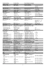
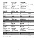
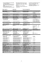
• Angaben im Kapitel „Technische Daten“
unbedingt einhalten.
• Bei Betrieb mit Wechselspannung ist eine
lösbare Verbindung zwischen Gerät und
Betriebserde erforderlich. Der Anschluss
entfällt bei Gleichspannung.
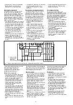
• Auslieferungszustand: Brücke zwischen
Y1-Y2
• Nur die Ausgangskontakte 13-14, 23-24,
33-34 sind Sicherheitskontakte. Aus-
gangskontakt 41-42 ist ein Hilfskontakt
(z. B. für Anzeige).
• Vor die Ausgangskontakte eine
Sicherung (s. techn. Daten) schalten,
um das Verschweißen der Kontakte zu
verhindern.
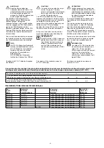
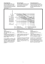
• Berechnung der max. Leitungslänge I
max
(Eingangskreis):
R
lmax
R
l
/ km
I
max
=
R
lmax
= max. Gesamtleitungswiderstand
(Eingangskreis)
R
l
/km = Leitungswiderstand/km
Wichtig für Querschlusserkennung:
Da diese Funktion nicht einfehlersicher ist,
wird sie von Pilz während der Endkontrolle
geprüft.
Wenn Gefahr besteht, dass Sie die
Leitungslängen überschreiten, empfehlen
wir folgende Prüfung nach der Installation
des Geräts:
1. Gerät betriebsbereit (Ausgangskontakte
geschlossen)
2. Die Testklemmen S12, S22 zur
Querschlussprüfung kurzschließen.
3. Die Sicherung im Gerät muss auslösen
und die Ausgangskontakte öffnen.
Leitungslängen in der Größenordnung der
Maximallänge können das Auslösen der
Sicherung um bis zu 2 Minuten verzögern.
4. Sicherung wieder zurücksetzen: den
Kurzschluss entfernen und die Versor-
gungsspannung für ca. 1 Minute abschal-
ten.
Operation
For operation:
• Only wire the unit when voltage is not
applied
• The power supply must comply with the
regulations for extra low voltages with
safe electrical separation (SELV, PELV)
in accordance with VDE 0100, Part 410.
• Use copper wiring that will withstand
60/75 °C.
• When connecting magnetically operated,
reed proximity switches, ensure that the
max. peak inrush current (on the input
circuit) does not overload the proximity
switch.
• Important details in the section "Technical
Data“ should be noted and adhered to.
• With AC operating voltage a detachable
connection is required between unit and
system earth. With DC operating voltage
this connection is not necessary.
• Unit supplied with Y1-Y2 linked
• Only the output contacts 13-14, 23-24,
33-34 are safety contacts. Output contact
41-42 is an auxiliary contact (e.g. for
signalling).
• To prevent contact welding, a fuse
(see technical detail) must be
connected before the output contacts.
• Calculate the max. Cable runs I
max
(Input
circuit):
R
lmax
R
l
/ km
I
max
=
R
lmax
= Max. Total cable resistance (Input
circuit)
R
l
/km = Cable resistance/km
Important for short circuit detection:
As the function for detecting shorts across
the inputs is not failsafe, it is tested by Pilz
during the final control check. However, if
there is a risk of exceeding the max. cable
length, we recommend a test to be made
after installing the unit as follows:
1. Unit ready for operation (output
contacts closed)
2. Short circuit the test (connection)
terminals S12, S22 for detecting shorts
across the inputs
3. The unit‘s fuse must be triggered and
the output contacts must open. Cable
lengths in the scale of the maximum
length can delay the fuse triggering for up
to 2 minutes.
4. Reset the fuse: remove the short circuit
and switch off the operating voltage for
approx. 1 minute.
Mise en oeuvre
Remarques préliminaires :
• L'appareil doit être câblé hors tension !
• L'alimentation doit satisfaire aux
prescriptions relatives aux tensions
extra basses avec une isolation
électrique de sécurité (SELV, PELV)
selon VDE 0100, partie 410.
• Utiliser uniquement des fils de cablâge en
cuivre 60/75 °C.
• Lors du raccordement de détecteurs de
proximité magnétiques, basés sur des
contacts Reed, veuillez vous assurer que
le courant de crête max. à la mise sous
tension (sur le circuit d'entrée) ne
surcharge pas les détecteurs de
proximité.
• Respecter les données indiquées dans le
chap. „Caractéristiques techniques“.
• Pour les tensions d'alimentation alternatives
UB~, une liaison amovible entre le boîtier et
la terre est exigée. Cette liaison n'est pas
nécessaire pour les relais alimentés en
24VCC.
• Pontages présents à la livraison: Y1-Y2
• Seuls les contacts 13-14, 23-24, 33-34 sont
des contacts de sécurité. Le contact 41-42
est un contact d’information
(ex. voyant)
• Raccordez une fusible (voir les
caractéristiques techniques) avant les
contacts de sortie afin d’éliminer tout
risque de fusion.
• Calcular les longueurs de câblage max
I
max
(Circuits d’entrée):
R
lmax
R
l
/ km
I
max
=
R
lmax
= résistivité de câblage totale max.
(Circuits d’entrée)
R
l
/km = résistivité de câblage/km
Important pour la détection de court-
circuit
La fonction de détection de court-circuit est
testé par Pilz lors du contrôle final.
Un test sur site en cas de risque de
dépassement de la longueur de câblage est
conseillé de la façon suivante :
1. Appareil en fonction (contacts de sortie
fermés)
2. Court-circuiter les bornes S12-S22 pour
générer un court-circuit
3. Le fusible interne du relais doit déclencher et
les contacts de sortie doivent s‘ouvrir. Le
temps de réponse du fuisible peut aller
jusqu‘à 2 min. si les longueurs de câblage
sont proches des valeurs maximales.
4. Réarmement du fusible : enlever le court-
circuit et couper l‘alimentation du relais
pendant au moins 1 min.
• Augmentation du nombre de contacts ou
du pouvoir de coupure par l’utilisation de
contacteurs externes.
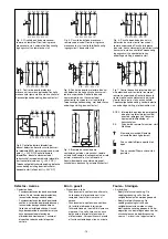
Montage
Le relais doit être monté en armoire ayant
un indice de protection mini IP54. Sa face
arrière permet un montage sur rail DIN.
Immobilisez l'appareil monté sur un rail DIN
vertical (35 mm) à l'aide d'un élément de
maintien comme par ex. un support ou une
équerre terminale.
• Increase in the number of safety contacts
available by connecting expander
modules
Installation
Install the safety relay in a panel
(min. IP54).
There is a notch on the rear of the unit for
DIN-Rail attachment.
If the unit is installed on a vertical mounting
rail (35 mm), ensure it is secured using a
fixing bracket such as end bracket.