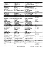
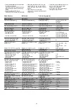
Pilz 19894-6NL-06 Operating Instructions Manual Download Page 17

- 17 -

Tiempos

Retardo a la conexión

rearme automático
U

B

 AC:

U

B

 DC:

rearme automático tras conexión
de red
U

B

 AC:

U

B

 DC:

rearme manual
U

B

 AC:

U

B

 DC:

rearme supervisado
U

B

 AC:

U

B

 DC:

Retardo a la desconexión

en caso de PARADA DE
EMERGENCIA
con interrupción del suministro eléctrico
U

B

 AC:

U

B

 DC:

Tiempo de recuperación  con la
frecuencia máxima de 1/s

tras PARADA DE EMERGENCIA
tras interrupción del suministro eléctrico

Simultaneidad

Tiempo de espera en caso de rearme
supervisado

Duración mínima de la senal de
arranque con arranque supervisado

Inmunidad a cortes de tensión
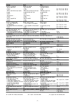
Medio ambiente

CEM

Vibraciones según EN 60068-2-6

frecuencia
amplitud

Condiciones climáticas

Distancias de fuga y dispersión
superficial según EN 60947-1

Grado de suciedad
Categoría de sobretensión

Tensión de aislamiento de
dimensionado

Resistencia tensión transitoria de
dimensionado

Temperatura ambiente

Temperatura de almacenaje

Grado de protección

lugar de montaje (p. ej. armario de
distribución)
carcasa
zona de bornes

Datos mecánicos

Material de la carcasa

carcasa
frente

Sección del conductor
exterior (bornes de tornillo)

1 conductor flexible
2 conductores multifilares de la
misma sección, flexibles con terminal,
sin revestimiento de plástico
flexibles sin terminal o con
terminal TWIN

Par de apriete para los bornes de
tornillo

Dimensiones Al x An x Pr

Peso

Tempi

Ritardo d’inserzione

Start automatico
U

B

 AC:

U

B

 DC:

Start automatico dopo attivazione
dell'alimentazione di rete
U

B

 AC:

U

B

 DC:

Start manuale
U

B

 AC:

U

B

 DC:

Start controllato
U

B

 AC:

U

B

 DC:

Ritardo tempo di scatto

in caso di arresto di emergenza

in caso di perdita di alimentazione
U

B

 AC:

U

B

 DC:

Tempo di ripristino par frequenza di
commutazione max. 1/s

dopo ARRESTO DI EMERGENZA
dopo perdita di alimentazione

Simultaneità

Tempo di attesa per start controllato

Durata minima impulso
di start con start controllato

Ininfluenza mancanza tensione

Dati ambientali

CEM

Oscillazioni secondo la norma
EN 60068-2-6

Frequenza
Ampiezza

Sollecitazione climatica

Caratteristiche dielettriche
secondo la norma EN 60947-1

Grado di contaminazione
Categoria di sovratensione

Tensione nominale di isolamento

Tensione di tenuta agli urti

Temperatura ambiente

Temperatura di magazzinaggio

Grado di protezione

Spazio di montaggio (p. es.
quadro elettrico ad armadio)
Custodia
Zona morsetti

Dati meccanici

Materiale impiegato per la custodia

Custodia
Parte frontale

Sezione trasversale del
conduttore esterno (morsetti a vite)

1 conduttore, flessibile
2 conduttori dello stesso diametro,
flessibile con capocorda, senza
guaina in plastica
flessibile senza capocorda o con
capocorda TWIN

Coppia di serraggio per i morsetti a
vite

Misure altezza x larghezza x profondità

Peso

Tijden

Inschakelvertraging

Automatische start
U

B

 AC:

U

B

 DC:

Automatische start na
netinschakeling
U

B

 AC:

U

B

 DC:

Handmatige start
U

B

 AC:

U

B

 DC:

Bewaakte start
U

B

 AC:

U

B

 DC:

Afvalvertraging

Bij noodstop

Bij uitvallen spanning
U

B

 AC:

U

B

 DC:

Resettijd bij max. schakelfrequentie
1/s

na noodstop
na uitvallen spanning

Gelijktijdigheid

Wachttijd bij bewaakte start

Min. startpulsduur bij bewaakte start

Maximale spanningsonderbreking

Omgevingscondities

EMC

Trillingsbestendigheid volgens
EN 60068-2-6

Frequentie
Amplitude

Klimaatcondities

Lucht- en kruipwegen volgens
EN 60947-1

Vervuilingsgraad
Oversturingscategorie

Nominale isolatiespanning

Nominale
stootspanningbestendigheid

Omgevingstemperatuur

Opslagtemperatuur

Beschermingsgraad

Inbouwruimte
(b.v. schakelkast)
Behuizing
Aansluitklemmen

Mechanische gegevens

Behuizingsmateriaal

Behuizing
Front

Doorsnede van de aansluitkabels
(schroefklemmen)

1 draad, flexibel
2 draden met dezelfde doorsnede,
flexibel met adereindhuls, zonder
kunststofhuls
Flexibel zonder adereindhuls of met
TWIN-adereindhuls

Aanhaalmoment voor
schroefklemmen

Afmetingen h x b x d

Gewicht

typ. 210 ms, max. 350 ms
typ. 270 ms, max. 600 ms

typ. 240 ms, max. 390 ms
typ. 270 ms, max. 600 ms

typ. 55 ms, max. 350 ms
typ. 70 ms, max. 600 ms

typ. 30 ms, max. 50 ms
typ. 40 ms, max. 70 ms

typ. 15 ms, max. 30 ms

typ. 55 ms, max. 80 ms
typ. 50 ms, max. 70 ms

50 ms
100 ms

U

B

 AC: 150 ms

U

B

 DC: 250 ms

30 ms

20 ms

EN 60947-5-1,
EN 61000-6-2

10 ... 55 Hz
0,35 mm

EN 60068-2-78

2
III / II

250 V

4,0 kV

-10 ... +55 °C

-40 ... +85 °C

IP54
IP40
IP20

PPO UL 94 V0
ABS UL 94 V0

0,20 ...4,0 mm

2

, 24 - 10 AWG

0,20 ... 2,5 mm

2

, 24 - 14 AWG

0,20 ... 2,5 mm

2

, 24 - 14 AWG

0,6 Nm

87 x 45 x 121 mm

U

B

 AC: 370 g

U

B

 DC: 270 g

No. es idéntico al Número de Pedido

"No." sta per "numero d'ordine"

No. is gelijk aan aan bestelnummer

Summary of Contents for 19894-6NL-06

Page 1: ...pplication The safety relay provides a safety related interruption of a safety circuit The safety relay meets the requirements of EN 60947 5 1 EN 60204 1 and VDE 0113 1 and may be used in applications...

Page 2: ...operation with short circuit detection Redundant input circuit Earth faults in the emergency stop circuit and shorts across the Emergency Stop push button are also detected Automatic reset The unit is...

Page 3: ...ut circuit Rlmax Rl km Imax Rlmax Max Total cable resistance Input circuit Rl km Cable resistance km Important for short circuit detection As the function for detecting shorts across the inputs is not...

Page 4: ...and the auxiliary contact 41 42 closes The status indicators go out Reactivation Close the input circuit For manual reset without monitoring press the button between S33 S34 For manual rest with monit...

Page 5: ...poussoir de validation S52 S34 S33 S11 S11 S22 S12 S21 S1 S2 S3 Y36 Y37 S52 S34 S33 S12 S11 S22 S12 S21 S1 S3 Y36 Y37 S11 S52 S12 S11 S22 S21 Y36 Y37 S34 S33 S3 Fehler St rungen Erdschluss Betrieb mi...

Page 6: ...tact fuse protection in accordance with EN 60947 5 1 IK 1 kA Blow out fusequick Blow out fuseslow Safety cut out Characteristic Max overall cable resistance Rlmax input circuits Single channel DC Sing...

Page 7: ...t Cable cross section screw terminals 1 core flexible 2 cores of the same cross section flexible with crimp connector without insulating sleeve flexible without crimp connector or with TWIN crimp conn...

Page 8: ...m ssen bei der Berechnung der Sicherheitskennwerte ber cksichtigt werden INFO Die SIL PL Werte einer Sicherheits funktion sind nicht identisch mit den SIL PL Werten der verwendeten Ger te und k nnen...

Page 9: ...allen Ausgangskontakten f r eine ausreichende Funkenl schung sorgen Bei kapazitiven Lasten sind eventuell auftretende Strom spitzen zu beachten Bei DC Sch tzen Freilaufdioden zur Funkenl schung einse...

Page 10: ...mm Dimensions in mm Dimensions en mm 121 4 76 75 2 95 87 3 42 45 1 77 EG Konformit tserkl rung Diese s Produkt e erf llen die Anforderun gen der Richtlinie 2006 42 EG ber Maschinen des europ ischen Pa...

Page 11: ...ci n orientada a la seguridad de un circuito de corriente de seguridad El dispositivo de seguridad cumple los requisitos de las normas EN 60947 5 1 EN 60204 1 e VDE 0113 1 y puede utilizarse en aplica...

Page 12: ...cador de estado CH 1 y CH 2 se apaga Los contactos de seguridad 13 14 23 24 33 34 se abren por redundancia el contacto auxiliar 41 42 se cierra Aislamiento respecto del rea no marcada y de los contact...

Page 13: ...60 75 C A la hora de conectar interruptores de proximidad magnetosensibles basados en contactos Reed prestar atenci n a que el pico m x de corriente de conexi n en el circuito de entrada no sobrecarg...

Page 14: ...Puentear S11 S52 Conectar el contacto normalmente cerrado del elemento disparador en S11 S12 y S21 S22 Circuito de realimentaci n Puentear Y1 Y2 o conectar los contactos normalmente cerrados conmutado...

Page 15: ...S12 S11 S22 S12 S21 S1 S3 Y36 Y37 S11 S52 S12 S11 S22 S21 Y36 Y37 S34 S33 S3 Fig 4 Circuito de entrada bicanal sin detecci n de corto circuito transversal rearme supervisado Circuito di ingresso bican...

Page 16: ...a conduttore totale max Rlmax circuiti di ingresso a singolo canale DC a singolo canale AC bicanale senza riconoscimento di cortocircuito traversale DC bicanale senza riconoscimento di cortocircuito t...

Page 17: ...ale di isolamento Tensione di tenuta agli urti Temperatura ambiente Temperatura di magazzinaggio Grado di protezione Spazio di montaggio p es quadro elettrico ad armadio Custodia Zona morsetti Dati me...

Page 18: ...n cuenta todas las unidades que intervienen en una funci n de seguridad INFORMACI N Los valores SIL PL de una funci n de seguridad no son id nticos a los valores SIL PL de los dispositivos utilizados...

Page 19: ...contactos de salida para prolongar la vida til En caso de cargas capacitivas controlar las puntas de tensi n que puedan crearse Utilizar diodos volantes para la extinci n de chispas de contactores DC...

Page 20: ...n Germany Dimensiones en mm Dimensioni in mm Afmetingen in mm 121 4 76 75 2 95 87 3 42 45 1 77 Declaraci n CE de conformidad Estos productos cumplen los requisitos de la Directiva de M quinas 2006 42...

Reviews: