PIAGGIO Liberty 125 Workshop Manual Download Page 70

1 mm

Pin retaining collar

- Remove the collar with the aid of 2 screwdrivers.

- Remove the 3 guide pins and the movable half-

pulley.

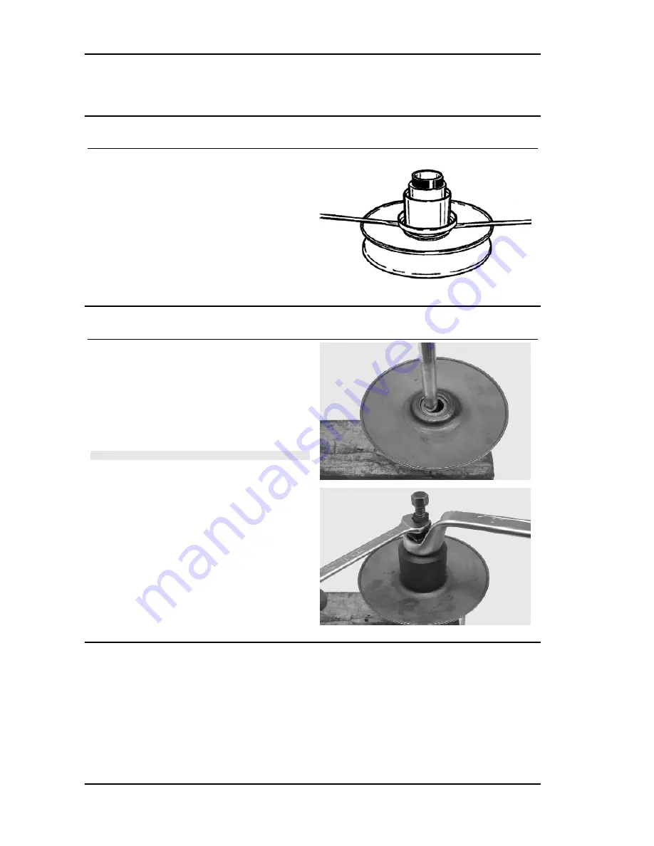
Removing the driven half-pulley bearing

- Remove the retaining ring using two flat blade

screwdrivers.

- Using a hammer and pin, knock the ball bearing

out as shown in the figure.

- Remove the roller bearing using the specific ex-

tractor.

N.B.

REST THE HALF-PULLEY ON A WOOD SURFACE TO
AVOID DAMAGING THE THREADED RINGLET OF THE
DRIVEN PULLEY UPON REMOVING IT.

Specific tooling

020375Y


Adaptor 28 x 30 mm

020376Y


Adaptor handle

020439Y


17 mm guide

Engine

Liberty 125 - 200 4tempi

ENG - 70

Summary of Contents for Liberty 125

Page 1: ...WORKSHOP MANUAL 633120 Liberty 125 200 4tempi...

Page 2: ...any changes to components parts or accessories which it considers necessary to improve the product or which are required for manufacturing or construction reasons Not all versions shown in this publi...

Page 3: ...the sections of this manual relating to specific tools along with the specific tool catalogue N B Provides key information to make the procedure easier to understand and carry out CAUTION Refers to sp...

Page 4: ......

Page 5: ...RACTERISTICS CHAR TOOLING TOOL MAINTENANCE MAIN TROUBLESHOOTING TROUBL ELECTRICAL SYSTEM ELE SYS ENGINE FROM VEHICLE ENG VE ENGINE ENG SUSPENSIONS SUSP BRAKING SYSTEM BRAK SYS CHASSIS CHAS PRE DELIVER...

Page 6: ...INDEX OF TOPICS CHARACTERISTICS CHAR...

Page 7: ...breathe in the dust produced by the wear of the friction material Even though the latter contains no asbestos inhaling dust is harmful Maintenance rules Use original PIAGGIO spare parts and lubricant...

Page 8: ...M381M 1001 VEHICLE IDENTIFICATION 200 Specification Desc Quantity Chassis prefix 200 ZAPM38400 1001 Engine prefix 200 M384M 1001 Dimensions and mass WEIGHT AND DIMENSIONS Specification Desc Quantity...

Page 9: ...6 mm Bore x stroke 200 72 x 48 6 mm Cubic capacity 125 124 cm Cubic capacity 200 197 cm Compression ratio 125 10 6 1 Compression ratio 200 9 5 1 Carburettor KEIHIN CVEK26 Engine idle speed approx 1 6...

Page 10: ...ark plug Champion RG6YC Frame and suspensions FRAME AND SUSPENSIONS Specification Desc Quantity Chassis Steel tube chassis Front suspension 32 Hydraulic telescopic fork travel 76 mm Rear suspension Hy...

Page 11: ...nverter The air enters the exhaust duct from the head and is purified by a black filter The system is fitted with a control valve that disa bles operation while decelerating to avoid unwan ted noise T...

Page 12: ...m air jet on the body 85 Tapered pin stamping NELA Throttle valve spring 130 180 gr Minimum jet 35 Idle air jet on the body 150 Idle mixture adjustment screw initial opening 1 Starter jet 42 Starter a...

Page 13: ...bloccaggio lubrificare i dadi prima del montaggio Montando dei nuovi prigionieri l operazione di serraggio dei dadi comprende l effettuazione di 3 rotazioni di 90 dopo il primo bloccaggio a 6 7 Nm pe...

Page 14: ...60 Coupling N 57 004 57 011 56 951 56 958 0 046 0 060 Coupling O 57 011 57 018 56 958 56 965 0 046 0 060 Coupling P 57 018 57 025 56 965 56 972 0 046 0 060 Coupling 1st oversize M1 57 197 57 204 57 14...

Page 15: ...crankshaft connecting rod AXIAL CLEARANCE BETWEEN CRANKSHAFT AND CONNECTING ROD 125 Name Description Dimensions Initials Quantity Half shaft transmission side 16 6 0 0 05 A D 0 20 0 50 Flywheel side h...

Page 16: ...CLEARANCE BETWEEN CRANKSHAFT AND CRANKSHAFT HALF BEARINGS 200 Name Description Dimensions Initials Quantity Crankshaft Category 1 28 998 29 004 Crankshaft Class 2 29 004 29 010 Crankcase Category 1 32...

Page 17: ...4 stroke engines AGIP FILTER OIL Oil for air filter sponge Mineral oil with specific additives for in creased adhesiveness AGIP GP 330 Grease brake control levers throttle grip Calcium complex soap ba...

Page 18: ...INDEX OF TOPICS TOOLING TOOL...

Page 19: ...0Y Tool for fitting steering seats 001467Y009 Driver for OD 42 mm bearings 001467Y013 Pliers to extract 15 mm bearings 002465Y Pliers for circlips 005095Y Engine support 008564Y Flywheel extractor Lib...

Page 20: ...moving fifth wheels from headstock 020055Y Wrench for steering tube ring nut 020074Y Support base for checking crankshaft alignment 020150Y Air heater support 020151Y Air heater 020193Y Oil pressure g...

Page 21: ...rip 020263Y Driven pulley assembly sheath 020287Y Clamp to assemble piston on cylinder 020306Y Punch for assembling valve sealing rings 020329Y MityVac vacuum operated pump 020330Y Stroboscopic light...

Page 22: ...Stores code Description 020331Y Digital multimeter 020332Y Digital rev counter 020333Y Single battery charger 020334Y Multiple battery charger Tooling Liberty 125 200 4tempi TOOL 22...

Page 23: ...de Description 020335Y Magnetic support for dial gauge 020357Y 32x35 mm Adaptor 020359Y 42x47 mm Adaptor 020360Y 52x55 mm Adaptor 020363Y 20 mm guide 020364Y 25 mm guide Liberty 125 200 4tempi Tooling...

Page 24: ...ion 020368Y driving pulley lock wrench 020375Y Adaptor 28 x 30 mm 020376Y Adaptor handle 020382Y011 adapter for valve removal tool 020409Y Multimeter adaptor Peak voltage detec tion Tooling Liberty 12...

Page 25: ...12Y 15 mm guide 020414Y 28 mm guide 020423Y Driven pulley lock wrench 020424Y Driven pulley roller casing fitting punch 020425Y Punch for flywheel side oil seal 020426Y Piston fitting fork Liberty 125...

Page 26: ...ng band 020428Y Piston position check support 020430Y Pin lock fitting tool 020431Y Valve oil seal extractor 020434Y Oil pressure control fitting 020444Y Tool for fitting removing the driven pulley cl...

Page 27: ...cription 020565Y Flywheel lock calliper spanner 020622Y Transmission side oil guard punch 494929Y Exhaust fumes analyser 020625Y Kit for sampling gas from the exhaust manifold Liberty 125 200 4tempi T...

Page 28: ...INDEX OF TOPICS MAINTENANCE MAIN...

Page 29: ...6000 KM 18000 KM 54000 KM 150 Action Engine oil replacement Hub oil level check Spark plug electrode gap check Air filter clean Engine oil change Oil filter net filter clean Valve clearance adjustmen...

Page 30: ...Cylinder ventilation system cleaning Odometer gear greasing Steering adjustment Brake control levers greasing Brake pads check condition and wear Brake fluid level check Transmission elements lubricat...

Page 31: ...d test See instructions in the Idle speed adjustment section AFTER 72 000 KM 270 Action Engine oil replacement Hub oil change Spark plug replacement Air filter clean Engine oil change Oil filter net f...

Page 32: ...m up Shut the engine down Disconnect the SAS check valve vacuum hose shown in the figure Seal the connection using a conical a cap Connect the Mitivac vacuum pump to the SAS control valve Start the va...

Page 33: ...BU RETTOR IS CLEAN AND THAT THE FUEL SUPPLY SYS TEM AND THE DEPRESSION SEALS WORK ADEQUATE LY N B IN CASE OF 1000 PPM UNBURNED HYDROCARBONS HC CHECK THE IGNITION SYSTEM THE TIMING SYS TEM THE VALVE CL...

Page 34: ...INDEX OF TOPICS TROUBLESHOOTING TROUBL...

Page 35: ...nd the valves grind or replace the valves Valve seat distorted Replace the head assembly Worn cylinder Worn or broken piston rings Replace the piston cylinder assembly or just the piston rings Rear wh...

Page 36: ...l pump with excessive clearance Perform the dimensional checks on the oil pump components Oil filter too dirty Replace the cartridge filter Oil level too low Restore the level using the recommended oi...

Page 37: ...ient braking INEFFICIENT OR NOISY BRAKING Possible Cause Operation Worn brake pads or shoes Replace the brake pads or shoes and check for brake disk or drum wear conditions Front brake disk loose or d...

Page 38: ...With the key switch set to ON jump the contacts 1 Blue Black and 5 Orange on the control unit connector If by operating the turn indicator control the lights are not stead ily on replace the control u...

Page 39: ...ally check the locking torque of the wheel axle nut the brake calliper and the disc Check that the swinging arm con necting the engine to the chassis and the rear shock absorber work properly Suspensi...

Page 40: ...INDEX OF TOPICS ELECTRICAL SYSTEM ELE SYS...

Page 41: ...ed turn signal and choke controller 4 Horn button 5 Turn signal switch 6 Light switch 7 Stop light switch on rear brake 8 Dual setting light bulb 12V 55 60W 9 Headlamp light bulb 10 High beam warning...

Page 42: ...rn signal light 25 Cable harness 26 Fuel level sender 27 Fuse holder assembly 28 Rear RHS turn signal light 29 License plate light bulb 30 License plate lamp 31 Battery 32 Starter relay 33 Starter mot...

Page 43: ...ed Vi Purple V Green VN Green Black BN White Black BBl White Blue GV Yellow Green Ar Orange Az Light Blue GrBl Grey Blue GrN Grey Black RBl Red Blue GR Yellow Red BlN Blue Black Conceptual diagrams Ig...

Page 44: ...atic starter 4 Key switch 5 Main fusible 15A 6 Battery 125 12V 9Ah 7 Battery 200 12V 12Ah 8 Headlamp relay 9 Light switch 10 High beam fuse 7 5A 11 Low beam and dashboard lights fuse 7 5A 12 Low beam...

Page 45: ...Voltage regulator 3 Pick up 4 Main fusible 15A 5 Battery 125 12V 9Ah 6 Battery 200 12V 12Ah 7 Starter relay 8 Starter motor 9 Start up button 10 Front and rear brake light button 11 Brake light filame...

Page 46: ...5 Key switch 6 Engine oil pressure sensor 7 Low oil pressure warning light 12V 1 2W 8 Low fuel warning light 12V 1 2W 9 Fuel gauge 10 Fuel level sender 11 Fuse 7 5 A 12 Immobilizer aerial 13 Low engin...

Page 47: ...tronic control unit 2 Indicators switch 3 4 Turn indicator bulbs 12V 10W 4 Turn signal warning light bulbs 12V 2W 5 Main fusible 15A 6 Battery 125 12V 9Ah 7 Battery 200 12V 12Ah 8 Horn 9 Fuse 7 5 A 10...

Page 48: ...ght turn indicator 4 Contact not connected 6 PIN CONNECTOR Specification Desc Quantity 1 Fuel gauge 2 High beam warning light 3 Engine oil warning light 4 Fuse 7 5 A 5 Low fuel warning light 12V 1 2W...

Page 49: ...F It remains activated for 48 hours in order not to affect the battery charge When the ignition switch is turned to ON the deterring blinker function is deactivated Subse quently a flash confirms the...

Page 50: ...ll run limited to 2000 rpm When trying to accelerate some evi dent loss of power may be felt Program the system with the MASTER Brown and SERVICE Blue keys as follows Insert the MASTER key turn it to...

Page 51: ...for 2 seconds and then di agnosis codes are transmitted with 0 5 sec flash es After the failure code indication a steadily on LED signals that ignition is disabled see the table 2 FLASH CODE Example...

Page 52: ...ystem is efficient when after switching over to ON only a 0 7 sec flash is detected see diagram In this case the engine can be started Example with programmed control unit trans ponder programmed key...

Page 53: ...the connector from the ECU and check for continuity between terminals 3 purple and 8 black see figure If unacceptable values are found repeat the in spection directly from the positive and negative te...

Page 54: ...HE MULTIMETER MUST BE SELECTED TO DETECT CONTINUOUS VOLTAGE Electric characteristic Pick Up voltage value Pick Up voltage value 2 Volt H V coil With the control unit and HV coil connected to the circu...

Page 55: ...and idle stability For this reason it is very important that the idle speed is adjusted as prescribed Specific tooling 020333Y Single battery charger 020334Y Multiple battery charger Stator check Dis...

Page 56: ...the voltage to set at about 12 V Start the engine and measure the current gen erated by the system with lights on and a high running engine In case the generated current value is lower than 8A repeat...

Page 57: ...the ECU Turn signals system check If the turn signal lights are faulty proceed as fol lows Detach the ECU connector and check for battery tension between terminal 5 Orange and earth with the key swit...

Page 58: ...onstant voltage charge equal to 14 40 14 70V Initial charge voltage equal to 0 3 0 5 for Nominal capacity Charge time 10 to 12 h recommended Minimum 6 h Maximum 24 h 3 Constant current battery charge...

Page 59: ...y on the vehicle ensuring that it is wired up properly 1 Hold the vertical tube 2 Look at the level 3 The float must be freed WARNING ONCE THE BATTERY HAS BEEN INSTALLED IN THE VE HICLE IT IS NECESSAR...

Page 60: ...ust be carried out with the specific battery charger single or multiple setting the battery charger selector to the type of battery to be recharged Connections to the power supply source must be imple...

Page 61: ...INDEX OF TOPICS ENGINE FROM VEHICLE ENG VE...

Page 62: ...val of the engine from the vehicle Remove the spark plug access cover Remove the helmet compartment Remove the entire muffler assembly Disconnect the spark plug cap Remove the 3 screws on the transmis...

Page 63: ...manifold Remove the rear shock absorber by loosening the top and bottom fixings Loosen the engine swingarm fixing nut from the right hand side of the vehicle and then remove the bolt from the left WAR...

Page 64: ...INDEX OF TOPICS ENGINE ENG...

Page 65: ...ecover the washer Remove the cap dipstick from the engine oil filling hole Remove the 10 screws and the earth cable fas tened under one of them Remove the transmission cover If this operation is perfo...

Page 66: ...riven pulley shaft bearing Remove the clip from the inside of the cover Use the specific tools to remove the bearing from the crankcase CAUTION USE AN APPROPRIATE REST SURFACE TO AVOID DAM AGING THE C...

Page 67: ...020357Y 32x35 mm Adaptor 020412Y 15 mm guide Removing the driven pulley Remove the spacer the clutch bell and the whole driven pulley unit N B THE UNIT CAN ALSO BE REMOVED WITH THE DRIVING PULLEY MOUN...

Page 68: ...ll Specific tooling 020074Y Support base for checking crankshaft alignment 020335Y Magnetic support for dial gauge Characteristic clutch bell inspection Limit eccentricity Admissible limit eccentricit...

Page 69: ...CENTRAL SCREW MUST NOT BE TIGHTENED WITH EXCESSIVE TORQUE AS THIS MAY DAMAGE THE PULLEY OR DEFORM THE SPECIFIC TOOL Specific tooling 020444Y Tool for fitting removing the driven pulley clutch 020444Y0...

Page 70: ...wo flat blade screwdrivers Using a hammer and pin knock the ball bearing out as shown in the figure Remove the roller bearing using the specific ex tractor N B REST THE HALF PULLEY ON A WOOD SURFACE T...

Page 71: ...lley bushing Characteristic Minimum admissible diameter 41 08 mm Standard diameter 41 035 mm Refitting the driven half pulley bearing Assemble a new roller case using the specific punch fit the bearin...

Page 72: ...glet with the appropriate protection sheath Make sure the pins and collar are not worn re assemble the pins and collar Use a greaser with a curved spout to lubricate the driven pulley unit with around...

Page 73: ...CAN CAUSE THE CLUTCH TO TEAR CAUTION DO NOT OPEN THE MASSES USING TOOLS SO AS TO PREVENT A VARIATION IN THE RETURN SPRING LOAD Characteristic Minimum thickness permitted 1 mm Support the driven pulle...

Page 74: ...ts direction of rotation Lock the driven pulley again using the specific tool Preload the clutch return spring with a traction rotation combined action and place the belt in the smaller diameter rolli...

Page 75: ...cking torque 55 60 Nm Refitting the driven pulley Reassemble the clutch bell and spacer Drive belt During the wear checks foreseen in the scheduled maintenance services at 6 000 km 18 000 km etc check...

Page 76: ...ate tool placed into the internal slots remove the nut with the built in Belleville washer Appropriate tools Specific tooling 020442Y Pulley lock wrench Remove the entire start up crown unit with the...

Page 77: ...the return rollers plate with the relative guide pads Inspecting the rollers case Check that the internal bushing is not abnormally worn and measure inner diameter N B DO NOT LUBRICATE OR CLEAN THE BU...

Page 78: ...ing the rollers as shown in the figure that is during insertion the closed side should be on the left side of the pulley thrust Mount the complete bushing unit on the driving shaft Open the rear pulle...

Page 79: ...is not possible choose the closest posi tion to the references Failure to do this may affect the cooling fan per formance The lock wrench operates on the start up crown If the torque limiter is worn...

Page 80: ...orques N m Locking torque 75 83 Refitting the transmission cover Check that there are 2 centring dowels and that the sealing gasket for the oil sump on the trans mission cover is adequately fitted Rep...

Page 81: ...r Take off the hub cover and relevant gaskets Removing the wheel axle Remove the intermediate gear and the complete hub cover Removing the hub bearings Check the state of the bearings being examined w...

Page 82: ...ey shaft bearing If it is necessary to remove the driven pulley shaft from the relevant bearing and oil seal remove driven pulley Extract the driven pulley shaft from its bearing Remove the oil guard...

Page 83: ...g the driven pulley shaft bearing Heat up the parts using the specific heat gun Specific tooling 020150Y Air heater support 020151Y Air heater Reassemble the driven pulley axle bearing positioning it...

Page 84: ...s shown in the figure to the hub using the adequate tools and with the seal lip towards the inside of the hub Specific tooling 020376Y Adaptor handle 020360Y 52x55 mm Adaptor Refitting the hub cover b...

Page 85: ...the correct position Screw the 7 screws to the specified torque po sitioning the support plate of the pipe in the posi tion shown in the figure Remove the control pin of the shoe taking care so as the...

Page 86: ...ines mentioned if they are losing a full circle at full gas we suggest to intervene on the vacuum socket inserting on the inlet manifold widening the hole from 0 4 mm to 1 5 mm Remember that such oper...

Page 87: ...ator and its wiring Refitting the stator Refit the stator and flywheel carrying out the re moval procedure in reverse tightening the retain ers to the specified torque Place the cable harness as shown...

Page 88: ...Check the integrity of the internal plastic parts of the flywheel and the Pick Up control plate Refitting the flywheel magneto Fit the flywheel being careful to insert the key properly Lock the flywh...

Page 89: ...ming system drive Remove the parts listed below first transmission cover belt driving pulley oil pump pulley cover and pinion separator washer Remove the tappet cover Remove the central screw fastener...

Page 90: ...ioning pad must be removed from the transmission side As regards the lower chain guide pad it may only be removed after the head has been removed N B IT IS ADVISABLE TO MARK THE CHAIN IN ORDER TO EN S...

Page 91: ...and in criss cross fashion Remove the head the two centring dowels and the gasket N B IN NEEDED THE HEAD MAY BE REMOVED WITH THE CAMSHAFT ROCKING LEVER PINS AND FIXING BRACK ET THE HEAD CAN ALSO BE RE...

Page 92: ...the wrist pin and the piston Remove the 3 piston rings from the piston N B BE CAREFUL NOT TO DAMAGE THE PISTON RINGS DUR ING REMOVAL Inspecting the small end Measure the internal diameter of the small...

Page 93: ...easure the outside diameter of the piston per pendicular to the gudgeon pin axis Measure 36 5 mm from the piston crown s shown in the figure N B THE PIN HOUSINGS HAVE 2 LUBRICATION CHANNELS FOR THIS R...

Page 94: ...ize They are also classified into 4 categories A A B B C C D D Inspecting the piston Carefully clean the seal housings Measure the coupling clearance between the seal rings and the grooves using suita...

Page 95: ...x1 A 0 10 0 30 Oil scraper ring 57x2 5 A 0 10 0 35 Compression ring 1st oversize 57 2 x 1 A 0 15 0 30 Oil scraper ring 1st oversize 57 2x1 A 0 10 0 30 Oil scraper ring 1st oversize 57 2x2 5 A 0 10 0 3...

Page 96: ...the gasket Provisionally fit the piston into the cylinder without any base gasket Assemble a dial gauge on the specific tool Set the dial gauge to zero at a contrast plane with an average precharge f...

Page 97: ...ratio 10 6 0 5 CYLINDER BASE GASKET THICKNESS Specification Desc Quantity Value measured 1 1 1 Thickness 0 8 0 05 Value measured 1 1 1 3 Thickness 0 6 0 05 Value measured 1 3 1 4 Thickness 0 4 0 05 L...

Page 98: ...with the word top or the reference mark facing the crown of the piston Offset the piston ring gaps on the three rings by 120 to each other as shown in the figure Lubricate the components with engine o...

Page 99: ...aximum admitted unevenness Head check 0 05 mm STANDARD DIAMETER Specification Desc Quantity Standard diameter A 32 5 32 525 Standard diameter B 20 20 021 Standard diameter C 12 12 018 Inspecting the t...

Page 100: ...valve seats VALVE SEAL SURFACE Specification Desc Quantity Inlet valve seal surface 2 4 2 8 mm Outlet valve seal surface 2 2 2 6 mm Inspecting the valve housings Remove any carbon formation from the v...

Page 101: ...nimum diameter admitted Inlet 4 96 mm Minimum diameter admitted Outlet 4 95 mm Standard clearance Inlet 0 013 0 040 mm Standard clearance Outlet 0 025 0 052 mm Maximum clearance admitted Inlet 0 062 m...

Page 102: ...WHEN NO LAPPING COM POUND IS LEFT CAREFULLY WASH THE CYLINDER HEAD AND THE VALVES WITH A SUITABLE PRODUCT FOR THE TYPE OF LAPPING COMPOUND BEING USED Insert the valves into the cylinder head Test the...

Page 103: ...the springs and insert the cotters in their seats Specific tooling 020382Y Valve cotters equipped with part 012 removal tool 020382Y011 adapter for valve removal tool Inspecting the cam shaft Inspect...

Page 104: ...Replace any defective or worn components Check there are no signs of scoring or wear on the rocking lever bolt Check there are no signs of wear on the pad from contact with the cam and on the jointed...

Page 105: ...crank shaft with the chamfer facing the insertion side Loop the timing chain around the sprocket on the crankshaft Fit the tensioner pad by the cylinder head Fit the spacer and the screw fastener Fit...

Page 106: ...d stop ring on the automatic valve lifter cam and fit the automatic valve lifter cam to the cam shaft Fit the automatic valve lifter return spring During this operation the spring must be loaded appro...

Page 107: ...rection use the supplements on the timing side as reference Assemble the screw fixing the housing to the crankcase to the specified torque and the 2 self threading screws joining the half shells Take...

Page 108: ...n the transmission chapter Remove the oil sump the by pass the chain compartment cover and the oil pump as in the lu brication chapter Remove the flywheel cover the fan the flywheel and the stator as...

Page 109: ...ankcase halves Remove the two screws and the internal cover shown in the diagram CAUTION WHILE OPENING THE CRANKCASES AND REMOVING THE DRIVING SHAFT CHECK THAT THE THREADED SHAFT ENDS DO NOT INTERFERE...

Page 110: ...does not have any defect the problem must be due to either excessive wear or wrong machining on the crankcase CAUTION THE CRANKSHAFT CAN BE REUSED WHEN THE WIDTH IS WITHIN THE STANDARD VALUES AND THE...

Page 111: ...be replaced and when cleaning the crankshaft be very careful that no impurities get in through the shaft s lubrication holes In order to prevent damaging the connecting rod bushings do not attempt cle...

Page 112: ...MAIN BUSHINGS AND CONNECTING ROD On the flywheel side crankcase half take partic ular care cleaning the oil ducts for the main bush ings the oil duct for the jet that lubricates the cylinder head and...

Page 113: ...thrusts caused by combustion and for this reason it is arranged opposed the cylinder To prevent shutters in the oil feeding channels the matching surface of the two half bearings must be perfectly or...

Page 114: ...BENDING DURING THE DRIVING OPERATION MAIN BEARINGS Specification Desc Quantity B Blue C Yellow E Green Refitting the crankcase halves Fit the internal bulkhead by locking the two screws to the prescri...

Page 115: ...appropriate tool to assemble the oil seal Fit a new O ring on the pre filter and lubricate it Insert the pre filter on the engine with its corre sponding cover to the specific torque N B REMOVE ANY EX...

Page 116: ...Conceptual diagrams Engine Liberty 125 200 4tempi ENG 116...

Page 117: ...4 2 atm Remove the appropriate tools once the meas urement is complete refit the oil pressure switch and washer tightening it to the prescribed torque and fit the fan cover If the oil pressure is outs...

Page 118: ...e threaded bar onto the base of the tool and extract the oil guard Specific tooling 020622Y Transmission side oil guard punch Refitting Prepare the new oil guard lubricating the sealing lip Warning do...

Page 119: ...ION ORIENT THE OIL GUARD BY POSITIONING THE CHAIN HOUSING CHANNEL FACING DOWNWARDS WHEN THE POSITION IS REACHED DO NOT RETRACT THE OIL GUARD FAILURE TO COMPLY WITH THIS RULE CAN CAUSE A WRONG POSITION...

Page 120: ...IN Oil pump Removal Remove the chain cover acting on the 3 retaining screws as shown in the figure and the relevant copper washer Extract the cover using the appropriate appen dages N B WITH THE AIM O...

Page 121: ...INITIAL DIRECTION OF ROTATION IS MAINTAINED Inspection Remove the two screws and the oil pump cover Remove the clip retaining the innermost rotor Remove and wash the rotors thoroughly with pet rol and...

Page 122: ...t or body Check there are no signs of scoring or wear on the oil pump cover If you detect non conforming measurements or scoring replace the faulty parts or the assembly Fit the pulley to the pump the...

Page 123: ...re and the 2 rear brake transmission fixing brackets Remove the spring the by pass piston and the gasket shown in the second image Inspecting the by pass valve Check the unloaded spring length Check t...

Page 124: ...ation system refer to the Crankcase and Crankshaft chapter re garding lubrication of the crankshaft and con necting rod Locking torques N m Locking torque 11 13 Fuel supply Disconnect the fuel supply...

Page 125: ...rate 20 cc Completely empty the fuel tank Remove the petrol delivery pipe and the low pressure pipe Loosen the clip and remove the cock Clean the tank and the filter of the cock with a specific solve...

Page 126: ...rew fastener shown in the dia gram the lever and the accelerator pump spring Remove the two screw fasteners shown in the diagram the venturi cover and the spring Remove the needle valve together with...

Page 127: ...pump piston together with the washer the boot the O ring and the spring as shown in the diagram Support the carburettor well and using a mallet and narrow drift remove the float pin from the throttle...

Page 128: ...carburettor body N B THIS OPERATION IS NECESSARY TO AVOID LOSING SPRAYER PARTS WHEN CLEANING THE CARBURETTOR BODY IF THE SPRAYER IS FORCED IN ITS HOUSING DO NOT ATTEMPT TO REMOVE IT AS THIS WILL ONLY...

Page 129: ...HAFT DO NOT REMOVE THROTTLE SHAFT CONNECTION SCREWS THE FIXING SCREWS ARE CAULKED AFTER THE ASSEMBLY AND THEIR REMOVAL DAMAGES THE SHAFT Refitting the carburettor Before refitting wash the carburettor...

Page 130: ...d to the throttle valve Check there are 5 ball bearing seals pressed into holes machined in the carburettor body Check that the two mating surfaces between the float bowl and the diaphragm are unblemi...

Page 131: ...ions Replace it in case of anomalies Fit the float together with the pin and rod in its position and lock it with its screw N B INTRODUCE THE RETURN SPRING ON THE FLOAT PLATE ADEQUATELY Level check Ho...

Page 132: ...oot Re fit the float together with the needle inserting the pin from the fuel inlet side Check the seal on the screw by introducing a little petrol into the float bowl Assemble a new boot on the float...

Page 133: ...y valve open Tighten the control arm screw fastener to the specified tightening torque Once assembled check the mechanism is work ing correctly Inspecting the valve and needle Undo the bayonet fitting...

Page 134: ...re of the carburettor offset towards the but terfly valve side Re fit the spring on the valve Re fit the vacuum chamber cover aligning the reference mark on the cover with the one on the diaphragm Tig...

Page 135: ...those specified replace it with a new one Re fit the auto choke unit to the carburettor en suring the O ring is correctly located and the knurled side of the clamping plate is facing down wards then t...

Page 136: ...331y on the sump using a cover with oil expressly pre pared for probes Start the motor and before adjusting the idle speed make sure that the oil temperature is be tween 70 80 C Using the rpm indicato...

Page 137: ...lve If it were difficult to adjustment CO check accurately That the carburettor is clean That the automatic starter is efficient Tapered pin housing efficiency Tank level adjustments N B THE EXTENSION...

Page 138: ...INDEX OF TOPICS SUSPENSIONS SUSP...

Page 139: ...GREASE IN THE AREAS MARKED WITH THE ASTERISK Handlebar Removal Remove the handlebar cover before carrying out this operation After removing the transmissions and discon necting the electrical termina...

Page 140: ...the upper screw 2 Add 30 cc 1 Fork PG oil SAE 20W oil for forks Refit all components Locking torques N m Upper screw tightening torque 20 to 25 Nm Lower screw tightening torque 20 to 25 Nm Steering co...

Page 141: ...g tube making sure mudflaps have been removed and the calliper dis connected Lower and upper races from frame To remove the bearing seats from the chassis use the appropriate tool as shown in the figu...

Page 142: ...WEEN THE CAP AND THE WHEEL AXLE Locking torques N m Rear wheel axle 104 126 Shock absorbers Removal To replace the shock absorber remove the rear cover and battery access flap to get and remove the sh...

Page 143: ...ING ATTACHMENTS AND THE PIN Changing the complete stand Work on the screws shown in the figure When refitting secure to the prescribed torque Locking torques N m Stand screw torque 18 5 to 19 Nm Expel...

Page 144: ...INDEX OF TOPICS BRAKING SYSTEM BRAK SYS...

Page 145: ...oupling bolts Fit the pads and bleed air from the system see previous paragraphs Position the caliper on the disc and fasten it to the support tightening the bolts Secure the tube connection to the ca...

Page 146: ...out the plungers inject shorts blasts of compressed air through the brake fluid pipe Check that the cylinders of the internal and external body of the calliper do not show scratches or signs of erosi...

Page 147: ...R LONGER THAN 20 SECONDS AFTER WASHING THE PIECES MUST BE DRIED WITH A BLAST OF COMPRESSED AIR AND A CLEAN CLOTH Locking torques N m Screw tightening calliper to the support 20 25 Calliper to tube con...

Page 148: ...oval To facilitate this operation remove the two calliper fixings With the calliper detached from its support but still connected to the brake fluid line remove the plastic cover by prising it with a...

Page 149: ...DURING THE OPERATIONS THE VEHICLE MUST BE ON THE STAND AND LEVEL N B DURING PURGING FREQUENTLY CHECK THE LEVEL TO PREVENT AIR GETTING INTO THE SYSTEM THROUGH THE PUMP WARNING BRAKING CIRCUIT FLUID IS...

Page 150: ...and drain the brake fluid through the bleeding screw located on the calliper and ac tuate the brake lever until no more fluid flows out Remove the oil pump from the handlebar remove the brake lever a...

Page 151: ...traces of oil diesel fuel grease etc They should be washed thoroughly in denatured alcohol before proceeding Reinstall the individual parts in the reverse order to the removal paying attention to the...

Page 152: ...INDEX OF TOPICS CHASSIS CHAS...

Page 153: ...ogation specifications it was concluded that the strap on the saddle is redun dant Please note that the passenger saddle comes without strap since last May The design number remains unchanged Side fai...

Page 154: ...he 2 side screws Driving mirrors With the register screw completely tightened screw the mirror stem all the way down on the handlebars Loosen the mirror and put it in the desired posi tion Loosen the...

Page 155: ...trument unit Remove the screw securing the instrument unit to the handlebar See also Front handlebar cover Instrument panel Remove the rear handlebar fairing Unscrew the 4 screws securing it and remov...

Page 156: ...ons Headlight assy Remove the front handlebar fairing Unscrew the 4 screws securing it and remove the headlight N B TO REPLACE THE HIGH BEAM DIPPED BEAM BULB THE RUBBER COVER MUST BE REMOVED AND THE S...

Page 157: ...s Remove the cover by holding it from the rear part and disconnect the turn indicator light connections See also Rear rack Seat Legshield Remove the countershield Remove the footrest Remove the front...

Page 158: ...signal connections See also Knee guard Footrest Knee guard Remove the 4 external screws of the counter shield and the 3 located inside the front glove box Use the bag clip to pull the countershield b...

Page 159: ...er with the key and with the anchoring tab facing down halfway on the lock body taking care that the insertion phase of the key is oriented matching ON the only position that enables the cylinder to g...

Page 160: ...ove the 2 external rubber caps of the screws securing the footrest and unscrew them Pull the footrest up being careful of the lower hooks See also Knee guard Frame central cover License plate holder R...

Page 161: ...e Rear mudguard Remove the 3 screws securing it on the left side including the 2 screws securing the air filter box Remove the screw on the side of the cooling cas ing Remove the mudguard by taking it...

Page 162: ...t compartment See also Frame central cover Frame central cover spoiler Remove the footrest Unscrew the two front screws securing it and then remove the spoiler from the bottom See also Footrest Fuel t...

Page 163: ...t and remove them Remove the speedometer transmission and brake hose then remove the mudguard N B WHEN REASSEMBLING BE CAREFUL TO POSITION THE 2 METAL GROMMETS TO AVOID ANY RUBBING AGAINST THE WHEEL T...

Page 164: ...Remove the two screws at the lower part of the inner shield fairing Remove the two screws located behind the front grille Chassis Liberty 125 200 4tempi CHAS 164...

Page 165: ...INDEX OF TOPICS PRE DELIVERY PRE DE...

Page 166: ...bar lock nut Steering lower ring nut Upper steering ring nut Electrical system Electrical system Main switch Headlamps high beam low beam position and parking lights and the respective warning lights...

Page 167: ...ND SEEK MEDICAL ATTENTION AT ONCE IF IT IS SWALLOWED IMMEDIATELY DRINK LARGE QUANTITIES OF WATER OR VEGETABLE OIL SEEK IMMEDIATE MEDICAL ATTENTION BATTERIES PRODUCE EXPLOSIVE GAS KEEP THEM AWAY FROM N...

Page 168: ...EED THE RECOMMENDED INFLATION PRESSURES OR TYRES MAY BURST Functional inspection Functional check up Braking system hydraulic Lever travel Braking system mechanical Lever travel Clutch Proper function...

Page 169: ...INDEX OF TOPICS TIME TIME...

Page 170: ...Engine ENGINE Code Action Duration 1 001001 engine from frame removal and re fitting Time Liberty 125 200 4tempi TIME 170...

Page 171: ...nkcase CRANKCASE Code Action Duration 1 001133 Engine crankcase Replacement 2 001153 Half crankcase gasket Replace ment 3 002031 Rear wheel hub bearings Replace ment Liberty 125 200 4tempi Time TIME 1...

Page 172: ...Crankshaft DRIVING SHAFT Code Action Duration 1 001117 Crankshaft Replacement 2 001099 Oil seal flywheel side Replacement Time Liberty 125 200 4tempi TIME 172...

Page 173: ...Cylinder assy CYLINDER GROUP Code Action Duration 1 001002 Cylinder Piston Replacement 2 001107 Cylinder piston Inspection clean ing Liberty 125 200 4tempi Time TIME 173...

Page 174: ...Cylinder head assy HEAD UNIT Code Action Duration 1 001045 Valves Replacement 2 001056 Head gasket change 3 001126 Head Replacement Time Liberty 125 200 4tempi TIME 174...

Page 175: ...er arms support assy ROCKING LEVER SUPPORT UNIT Code Action Duration 1 001044 Camshaft Replacement 2 001148 Rocking lever valve Replacement 3 001049 Valves Adjustments Liberty 125 200 4tempi Time TIME...

Page 176: ...placement 2 001088 Head cover gasket Replacement 3 001159 Oil vapour recovery tank Service 4 001093 Spark plug Replacement 5 001097 Cooling hood Replacement 6 001091 Head cover sealing ring 7 001074 O...

Page 177: ...Chain tensioner CHAIN TIGHTENER Code Action Duration 1 001129 Chain tensioner Service and Re placement 2 001124 By pass lubrication Replacement Liberty 125 200 4tempi Time TIME 177...

Page 178: ...L FILTER Code Action Duration 1 001123 Oil filter Replacement 2 001160 Oil pressure sensor Replacement 3 003064 Engine oil Change 4 001102 Mesh oil filter Replacement Clean ing Time Liberty 125 200 4t...

Page 179: ...087 Flywheel cover Replacement 2 001163 Secondary air exhaust manifold Replacement 3 001161 Secondary air filter Replacement Cleaning 4 001174 SAS valve Replacement 5 001164 Secondary air crankcase ma...

Page 180: ...DRIVEN PULLEY CLUTCH Code Action Duration 1 001155 Clutch bell housing Replacement 2 001022 Clutch Replacement 3 001012 Driven pulley Overhaul 4 001110 Driven pulley Replacement Time Liberty 125 200 4...

Page 181: ...chain Replacement 2 001125 Chain guide pads Replacement 3 001042 Oil pump Overhaul 4 001112 Oil pump Replacement 5 001130 Oil sump Replacement 6 001100 Oil seal clutch side Replacement 7 001122 Oil p...

Page 182: ...GEAR ASSEMBLY Code Action Duration 1 004125 Rear wheel axle Replacement 2 001156 Gear reduction unit cover Replace ment 3 003065 Gearcase oil Replacement 4 001010 Gear reduction unit Inspection Time...

Page 183: ...LLEY Code Action Duration 1 001066 Driving pulley Removal and refitting 2 001086 Driving half pulley replace 3 001177 Variator rollers slides Replace ment 4 001011 Driving belt Replacement Liberty 125...

Page 184: ...Transmission cover Starter motor Time Liberty 125 200 4tempi TIME 184...

Page 185: ...nt 2 001017 Starter sprocket wheel Replace ment Flywheel magneto MAGNETO FLYWHEEL Code Action Duration 1 001109 Cooling fan Replacement 2 001173 Rotor Replacement 3 001067 Stator Removal and Refitting...

Page 186: ...g duct BELT COOLING PIPE Code Action Duration 1 001131 Transmission air inlet Replacement 2 001132 Transmission air inlet pipe Replace ment 3 001170 Air manifold replacement Time Liberty 125 200 4temp...

Page 187: ...urettor heating resistor Re placement 2 001013 Intake hose Replacement 3 004122 Carburettor filter bellow Replace ment 4 001081 Automatic choke Replacement 5 001008 Carburettor Inspection 6 001063 Car...

Page 188: ...justment 3 001095 Muffler guard Replacement Silencer fixing Please take note that starting from chassis serial number ZAPM3810000003971 the two M8 x 50 silencer fixing flaged head screws have been rep...

Page 189: ...Air cleaner AIR CLEANER Code Action Duration 1 001014 Air filter Replacement Cleaning 2 001015 Air filter box Replacement Liberty 125 200 4tempi Time TIME 189...

Page 190: ...Frame FRAME Code Action Duration 1 004001 Chassis Replacement 2 004004 Stand Replacement 3 001053 Stand bolt Replacement Time Liberty 125 200 4tempi TIME 190...

Page 191: ...eplacement 2 004149 Shield central cover Replacement 3 004064 Front shield front section Removal and refitting 4 004079 Rear footrest Replacement 5 004053 Spoiler Replacement 6 004015 Footrest Disasse...

Page 192: ...ove box remote opening linkage Replacement 2 004065 Knee guard Removal and refitting 3 004131 Rear rack mounting bracket Re placement 4 004082 Glove box packing Replacement 5 004081 Glove comparment d...

Page 193: ...ER Code Action Duration 1 004059 Spark plug inspection flap Replace ment 2 004106 Under saddle band Replacement 3 004085 Fairing 1 Replacement 4 004013 Side rear bumper pipes Replace ment Liberty 125...

Page 194: ...ompartment UNDERSEAT COMPARTMENT Code Action Duration 1 005046 Battery cover Replacement 2 004016 Helmet compartment Removal and Refitting 3 001027 Filter bellow Replacement Time Liberty 125 200 4temp...

Page 195: ...ense plate holder support Re placement 2 005048 Licence plate holder Replacement 3 005131 number plate light support Replace ment 4 005031 Licence plate light bulb Replace ment 5 005032 number plate l...

Page 196: ...Mudguard MUDGUARD Code Action Duration 1 004002 Front mudguard Replacement 2 004009 Rear mudguard Replacement Time Liberty 125 200 4tempi TIME 196...

Page 197: ...168 Fuel tank cap Replacement 2 005010 Tank float Replacement 3 004112 Cock carburettor hose Replace ment 4 004005 Fuel tank Replacement 5 004007 Fuel valve Replacement 6 004109 Fuel tank breather Rep...

Page 198: ...Rear shock absorber REAR SHOCK ABSORBER Code Action Duration 1 003007 Rear shock absorber Removal and Refitting Time Liberty 125 200 4tempi TIME 198...

Page 199: ...Steering column bearings STEERING COLUMN BEARINGS Code Action Duration 1 003002 Steering fifth wheels Replacement 2 003073 Steering clearance Adjustment Liberty 125 200 4tempi Time TIME 199...

Page 200: ...eplace ment 2 004018 Handlebar front section Replace ment 3 005078 Odometer glass Replacement 4 005076 Clock Pile Replacement 5 005014 Odometer Replacement 6 005038 Instrument panel warning light bulb...

Page 201: ...r Removal and refitting 5 005017 Stop switch Replacement 6 002024 Front brake pump Removal and Re fitting 7 003061 Accelerator transmission Adjust ment 8 002060 Complete throttle control Replace ment...

Page 202: ...Swing arm SWINGING ARM Code Action Duration 1 001072 Engine frame swinging arm fitting Replacement 2 003080 Swinging arm on frame Replace ment Time Liberty 125 200 4tempi TIME 202...

Page 203: ...Duration 1 002007 Front brake shoes pads Remov and Refitt 2 002039 Front brake line Replacement 3 002021 Front brake hose Remov and Re fitt 4 002047 Front brake fluid and system bleed ing plug Repl L...

Page 204: ...Seat SEAT Code Action Duration 1 004003 Saddle Replacement 2 004008 Luggage rack Replacement 3 004062 Luggage rack cover Replacement Time Liberty 125 200 4tempi TIME 204...

Page 205: ...5067 Front turn indicator bulb Replace ment 4 005008 Front headlamp bulbs Replacement 5 005005 Taillight Replacement 6 005066 Rear light bulbs Replacement 7 005028 Rear light assembly glass Replace me...

Page 206: ...eplacement Grease tone wheel or drive Please take note that the code has been intro duced 900001 Tone wheel drive greasing 15 Never mistake the codes 002011 movement sen sor replacement and 005089 ton...

Page 207: ...AR WHEEL Code Action Duration 1 002002 Rear brake pads shoes Repl 2 004126 Rear wheel tyre Replacement 3 001016 Rear wheel Replacement 4 001071 Rear wheel rim Removal and Refit Liberty 125 200 4tempi...

Page 208: ...ctric system Removal and reas sembly 4 001094 Spark plug cap Replacement 5 001069 HV coil replace 6 005052 Fuse Replacement 7 005025 Battery fuse box Replacement 8 005009 Voltage regulator Replacement...

Page 209: ...2 005006 Light or turning indicator switch Re placement 3 005040 Horn button Replacement 4 005003 Horn Replacement 5 005041 Starter button Replacement 6 005016 Key switch Replacement 7 004096 Lock se...

Page 210: ...TRANSMISSIONS Code Action Duration 1 002051 Odometer transmission assembly Replacement 2 002049 Odometer cable Replacement 3 002053 Rear brake transmission complete replacement Time Liberty 125 200 4t...

Page 211: ...n Duration 1 003010 Front suspension Service 2 003048 Fork oil seal Replacement 3 003076 Fork leg Replacement 4 003079 Fork stem Replacement 5 003051 Complete fork replace 6 003069 Front fork oil Repl...

Page 212: ...ettor 11 125 129 187 F Fuel 37 124 162 197 H Headlight 156 Horn I Identification 8 Instrument panel 155 M Maintenance 7 29 Mirrors 154 O Oil filter 178 S Shock absorbers 142 Spark plug 53 Start up T T...

Reviews: