Page 24 / 25
2018-11-13
P725T0010, valid for P-725
Physik Instrumente (PI ) GmbH & Co. KG, Auf der Roemerstr. 1, 76228 Karlsruhe/Germany
Phone +49 721 4846-0, Fax +49 721 4846-1019, Email [email protected],
www.pi.ws
P-725.xCD, P-725.xCA, P-725.CDD
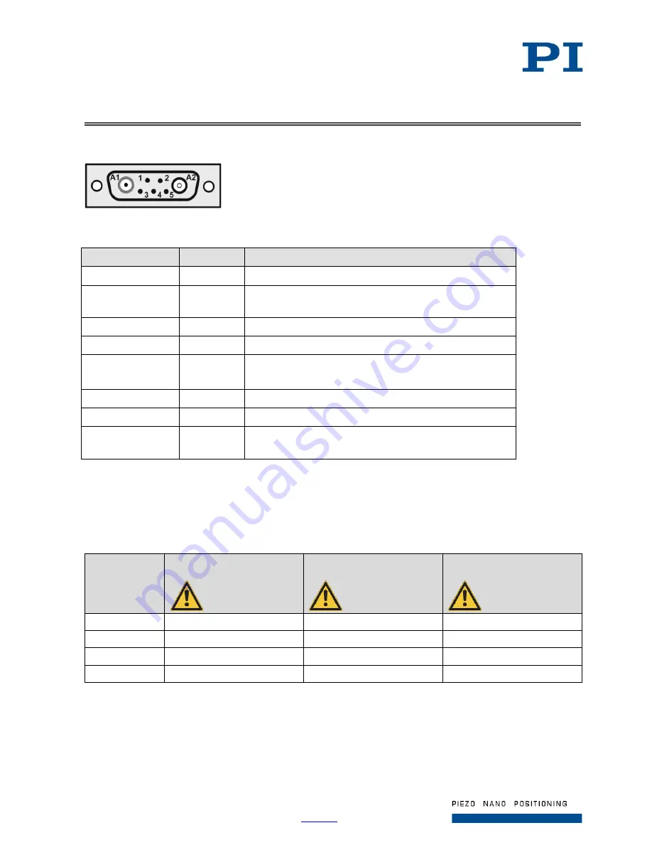
Figure 14: Sub-D 7W2 (m) connector, front view
Pin
Signal
Function
A1 inner conductor
Input
Piezo v
A2 inner conductor
Output
Probe sensor signal
(nonmoving part of the capacitive sensor)
A2 outer conductor
GND
Shield
1
Bidirectional Data line for ID chip
2
GND
Shield of Target
Ground of ID chip when switched on
3
Input
Piezo voltage –
4
N.C.
Not connected
5
Input
Target sensor signal
(movable part of the capacitive sensor)
The connector shell is connected to the cable shield.
Maximum Ratings
The P-725 is designed for the following maximum ratings:
Model
Maximum operating
voltage
Maximum operating
frequency (unloaded)
Maximum power
consumption
P-725.1xx
-20 to 120 V
150 Hz
13 W
P-725.2xx
-20 to 120 V
100 Hz
17.4 W
P-725.4xx
-20 to 120 V
75 Hz
17.4 W
P-725.xDD
-20 to 120 V
300 Hz
4.7 W


