background image


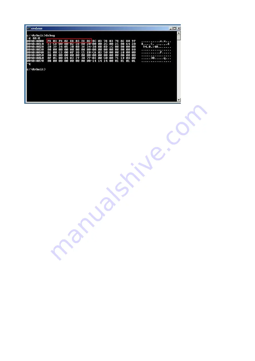
In the first 4 * 2 bytes in the system stands the COM ports are known: 
F8 03 COM1
F8 02 COM2
E8 03 COM3
E8 02 COM4
00 00 Empty entry (here not available) 
In our case there is simply no more free COM port. When an empty entry is present, then cant be 
used only the required for this IRQ. 
COM1 and COM3 uses both the same IRQ4
COM2 and COM4 uses both the same IRQ3 

S5VCOM uses COM3 in the DOS box, but my S5 software can only use COM1 or COM2 (eg.:
S5 V3.02)


Try to integrate in the system the from system existing COM 1/2 interface as a COM 3/4 (possibly 
by a jumper). 

My Windows software can not access the PG-USB-cable / USB-RS232-converter, although this
is set in the control panel correctly and it worked before. It appears the error message that the
COM port is already occpied or is not accessible.


The S5VCOM driver opens this COM port to communicate about even if no MSDOS box is open. 
The Windows program would now like to open the same COM port. This fails. 
Quit the S5VCOM program (tray icon), thereafter an access from Windows is possible here, but 
from a MSDOS box is not. By restarting the program out from the startup folder, then can be 
worked under MSDOS again. Access under Windows and under MSDOS exclude each other! 

It still works not, though the driver is loaded and the tray icon appears.


Double click the tray icon and select from the system menu "Information about ..." 

Handbook PG-USB

Page 20 of 21

Summary of Contents for 9359-1

Page 1: ...PG USB user manual english Art Nr 9359 1 Art Nr 9359 1 05M 14 05 2019 PI 2019...

Page 2: ...the Step5 addition driver for PG USB S5 LAN USB RS232 converter 6 4 Control elements 7 4 1 Status LEDs 7 5 Implementing 7 5 1 Programming software to use with direct access 8 5 1 1 PG2000 f r S5 V5 10...

Page 3: ...oller 1 1 Basic circuit diagram 2 System requirements 2 1 Operating system s Windows 98 SE Windows ME NT 2000 Windows XP Windows Vista Windows 7 2 2 Software PLC programming software eg PG2000 Step 5...

Page 4: ...dows Setup Wizard in the previously extracted folder 3 During the installation you were asked if you want to continue this Confirm this message with Continue 4 Once the USB driver is installed you hav...

Page 5: ...starting the driver it will be displayed If properly installed appears at the right bottom of the screen another tray icon On this icon you can see if the PG USB cable USB RS232 converter is recogniz...

Page 6: ...tallation wizard where you point into the folder where you unzipped the new USB driver Now you can continue to work with the PG USB or USB RS232 converter The possible patch of Step5 software must not...

Page 7: ...delete the already installed drivers If the COM port of the PLC VCOM is changed afterwards the Step5 drivers must be reinstalled Attention For the Step5 Siemens software the COM port must be are betw...

Page 8: ...requirements as descript in the chapter system requirements In addition please make sure that the module is properly connected 5 1 Programming software to use with direct access After you have adjust...

Page 9: ...ays only one block from PLC FB names Bst Info and check COM Ports 5 Save your configuration by pressing OK 6 Now the software is ready to establish a connection to the PLC Click the symbol Open and af...

Page 10: ...e to online The window should display the AG type 5 The connection with the PLC is successfully established when the operating mode changes to Online 5 1 3 Windows Control Center WinCC v6 0 1 Start Wi...

Page 11: ...t is shown in the left part of the main window 6 For a proper working communication with the PLC there must be defined how the software has to communicate with the PLC Therefore right click on Tag Man...

Page 12: ...10 Confirm with OK until you are back to the main window 11 Now you can with start the communication and with this end it again 5 1 4 Windows Control Center flexible 2004 WinCC flexibel v5 2 0 0 1 St...

Page 13: ...Data bits 8 Stop bits 1 6 Now you can start with your work If you have finished work you can transfer this project to the panel by reading the next steps 7 Choose Transfer Settings from the sub menu T...

Page 14: ...symbol 3 The next dialog askes you which operator panel you are using Mark the used panel e g TP 170A 4 Next leads you to a new dialog Type in the specfic fields the name of the PLC device and choose...

Page 15: ...your work If you have finished working on this project you can go on with the next steps 9 If you want to transfer you project to the panel you have to generate the project first This can be done with...

Page 16: ...bility to set up a lot of configuration data about the communication with your PLC 4 Choose the first registry card Interface standard and set up the configuration data as descriped below Interface Se...

Page 17: ...the OK button 7 Back in the main window press the PC Block List button for testing the new established communication configuration 8 9 Please wait a moment for the software to read the desired blocks...

Page 18: ...Data line BiDi 3 D Data line BiDi 4 GND Ground In Important Please do not lengthen this side this side also supports the 5V DC power supply max cable length are 5 meters A longer cable would decrease...

Page 19: ...s on the CD While copying files appears an error message that copying is not possible This can have several causes Possibly you not have enough space left on the hard disk the program is already insta...

Page 20: ...G USB cable USB RS232 converter although this is set in the control panel correctly and it worked before It appears the error message that the COM port is already occpied or is not accessible The S5VC...

Page 21: ...ver the image It appears additional control elements where you click ONLY on the button VCOMLOG Confirm with OK In the installation directory of S5VCOM was generated the file VCOM LOG Send this to us...

Reviews: