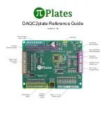
Connector
Refer to the diagram at the top of this page as well as the one below to locate the Digital Output terminals:
Specifications
● Each of the 8 Digital Outputs is an open drain transistor
● Maximum sink current is 3A
● Maximum load voltage is 30VDC
● On voltage is typically less than 50mV with a load current of 1A
● When using a relay or solenoid, the high side power supply should be connected to the "Flyback
Protection" terminal
● If necessary, the on-board 5VDC is available on pin 10. If you choose to use it, then make sure your
power supply can provide enough current for your Raspberry Pi (~700mA), your Pi-Plates (~100mA for
each DAQC2plate with all LEDs on) and any components you connect to a DOUT terminal.
● To generate a simple digital signal output, connect a 4.7K resistor between 5VDC and the DOUT pin
you wish to use. Note that the output will be inverted i.e. setting the pin will make the output zero volts
while clearing it will make it 5VDC.
Functions
addr
must be in the range of 0 through 7
bit
must be in the range of 0 through 7
● setDOUTbit(addr, bit) - set single bit. Note that this turn ON the transistor and any device attached to it.
● clrDOUTbit(addr, bit) - clear single bit. Note that this turn OFF the transistor and any device attached to
it.
● toggleDOUTbit(addr, bit) - toggle a single bit
● setDOUTall(addr,byte) - control all eight bits at once. The byte value must be in the range of 0 through
255.


