Delivery Contents / Technical Data
PHYTEC Meßtechnik GmbH 2004 L-608e_4
17
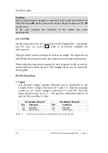
Figure 3:
Standard Connections for the I/O Pin as Input
•
Output
For use as an output pin, Pin 26 or Pin 15 is connected to Ground
through a circuitry transistor (for example Pin 24 for X3, Pin 19
for X6), if the program sets the Pin to a logical „1“.
If the program sets the pin to logic „0“, then the transistor is
disabled and thus, there is no connection between pin 26 or Pin 15
and Ground.
In order to use the output, an external power supply, in the range of
5 V and 28 V, is required. It is also possible to use the power
supply pin (pin 25 of X3) for power supply.
Figure 3 and Figure 4 depict two possible connections.
a)Connection from the Grabbers‘ power supply pin
b) Connection from external DC voltage supply source
Figure 4:
Standard Connections for the I/O Pin as Output
Summary of Contents for eGrabber-4plus
Page 8: ...eGrabber 4plus PHYTEC Meßtechnik GmbH 2004 L 608e_4 ...
Page 10: ...eGrabber 4plus PHYTEC Meßtechnik GmbH 2004 L 608e_4 ...
Page 56: ...eGrabber 4plus 46 PHYTEC Meßtechnik GmbH 2004 L 608e_4 ...
Page 80: ...eGrabber 4plus 70 PHYTEC Meßtechnik GmbH 2004 L 608e_4 ...
Page 81: ...Part 2 Programmer s Manual PHYTEC Meßtechnik GmbH 2004 L 608e_4 71 Part 2 Programmer s Manual ...
Page 82: ...eGrabber 4plus 72 PHYTEC Meßtechnik GmbH 2004 L 608e_4 ...
Page 188: ...eGrabber 4plus 178 PHYTEC Meßtechnik GmbH 2004 L 608e_4 ...
Page 192: ...eGrabber 4plus 182 PHYTEC Meßtechnik GmbH 2004 L 608e_4 ...
Page 204: ...eGrabber 4plus 194 PHYTEC Meßtechnik GmbH 2004 L 608e_4 ...
Page 206: ...Published by PHYTEC Meßtechnik GmbH 2004 Ordering No L 608e_4 Printed in Germany ...


