Processor Rear Panel
Processor Rear Panel
TRIGGER SW IN
TRIGGER SW IN
BNC type connector, one of two trigger inputs. This input requires a contact closure
BNC type connector, one of two trigger inputs. This input requires a contact closure
between the connector center conductor and shield in order to generate a trigger.
between the connector center conductor and shield in order to generate a trigger.
The Processor response to a trigger input is programmed by SW2. The Processor
The Processor response to a trigger input is programmed by SW2. The Processor
waits until the start of the next frame to trigger if SW2 is set to “trigger”. If SW2 is
waits until the start of the next frame to trigger if SW2 is set to “trigger”. If SW2 is
set to “reset & trigger” the Processor will start a new frame the instant the trigger is
set to “reset & trigger” the Processor will start a new frame the instant the trigger is
received, and mark it as the trigger point. A simplified schematic for the input is as
received, and mark it as the trigger point. A simplified schematic for the input is as
follows:
follows:
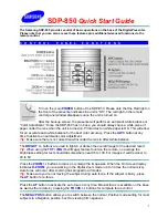
TRIGGER SW IN CIRCUIT DIAGRAM
TRIGGER SW IN CIRCUIT DIAGRAM
EXT IN
EXT IN
A BNC-type connector that accepts a synchronizing signal input from another
A BNC-type connector that accepts a synchronizing signal input from another
FASTCAM ultima SE, allowing the user to synchronize two or more units. Use the
FASTCAM ultima SE, allowing the user to synchronize two or more units. Use the
menu’s Sync Select function to enable this input, (See page 3-
menu’s Sync Select function to enable this input, (See page 3- 14).
14).
SYNCHRONIZING TWO OR MORE PROCESSORS TOGETHER
SYNCHRONIZING TWO OR MORE PROCESSORS TOGETHER
Connect the EXT OUT of one Processor to the EXT IN of the next Processor. The
Connect the EXT OUT of one Processor to the EXT IN of the next Processor. The
EXT OUT of the second Processor can then drive a third Processor, and so on. The
EXT OUT of the second Processor can then drive a third Processor, and so on. The
EXT OUT must be set to V Sync with SW2. You may need to increase the V Sync
EXT OUT must be set to V Sync with SW2. You may need to increase the V Sync
pulse width as you increase cable length between Processors. Configure EXT IN to
pulse width as you increase cable length between Processors. Configure EXT IN to
Reset & Trigger.
Reset & Trigger.
10K
+ 5V
220
0.1µf
TRIGGER
SWITCH IN
2-6
2-6
Summary of Contents for FASTCAM ultima SE
Page 2: ...Notes Notes...
Page 6: ...Notes Notes...
Page 14: ...Notes Notes...
Page 15: ...PHOTRON FASTCAM ultima SE PHOTRON FASTCAM ultima SE 2 1 2 1...
Page 24: ...Notes Notes...
Page 26: ...Notes Notes...
Page 46: ...Notes Notes...
Page 48: ...Notes Notes...
Page 56: ...Notes Notes...
Page 76: ...Notes Notes...
Page 78: ...Notes Notes...
Page 86: ...Notes Notes...
Page 88: ...Notes Notes...