21
There are two buttons for each of the available
options.
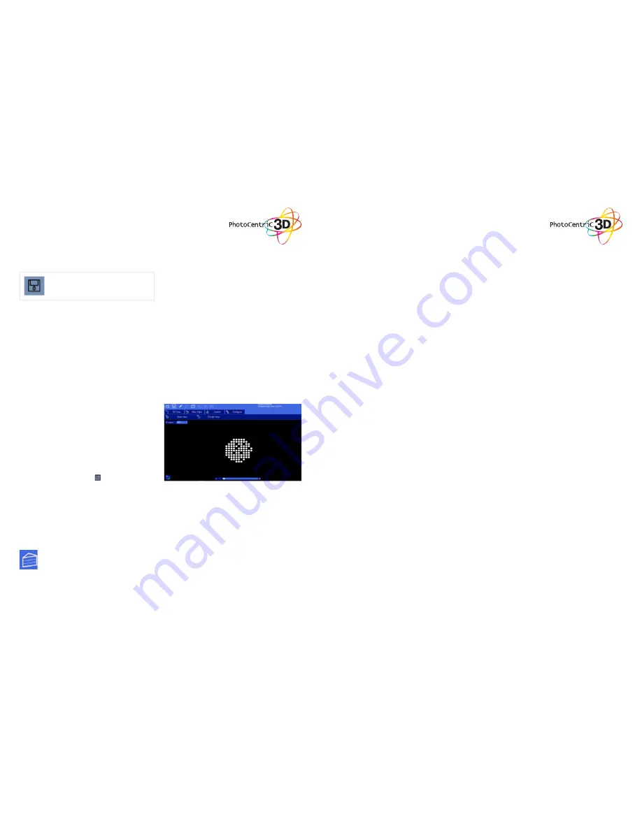
• The first option has the same name as the
screen itself (Slice View). In this setting we can
see (as shown in the image) each successive
layer of the generated “Slicing”. With the lower
bar we can scroll through the entire slicing
result to check each of the layers. In the upper
left corner we can see the total number of
layers that have been generated. In the lower
left corner we have a ( ) button to turn the
screen on and expose the selected layer.
• G-Code View: On this screen you can see
the G-code generated during the “Slicing”
operation. This option is intended for advanced
users. We recommend to leave this screen
untouched.
12. Slicing a Model
11. Slice View
In the Slice View screen we get the following
information:
After one or more models have been loaded and
manipulated on the build platform, the entire
scene can be saved as an STL model for later use.
Simply click on the ‘File->Save Scene STL’ menu
item to save the scene model. This will flatten all
models in a scene into a single STL file. Scenes
can also be saved to CWS files. These scene files
can be used to create a scene with supports,
slice the scene, and later load to print your scene
without the need for re-slicing.
Click to save the current object as a .STL or
.CWS file. The .CWS format allows you to
prepare a scene to be printed repeatedly in the
future, together with supports and positioning.
10. Saving a Scene
Once you have loaded one of the models,
configured your machine profile, and
configured your build & slicing profile, you
can slice a model. Choose the slice icon
from the toolbar ro bring up the slicing
screen.
22
You can change the currently selected slicing
profile to use. Click the ‘Slice’ button to begin
slicing. You can stop slicing by pressing
the ‘Cancel’ button. If your slicing profile is
configured to export images, a progress bar
will appear here. Otherwise, just the gcode for
the scene will be generated and the images
will be rendered during build-time.


