17
6. DETAILED
CREATION WORKSHOP
SOFTWARE
INSTRUCTIONS
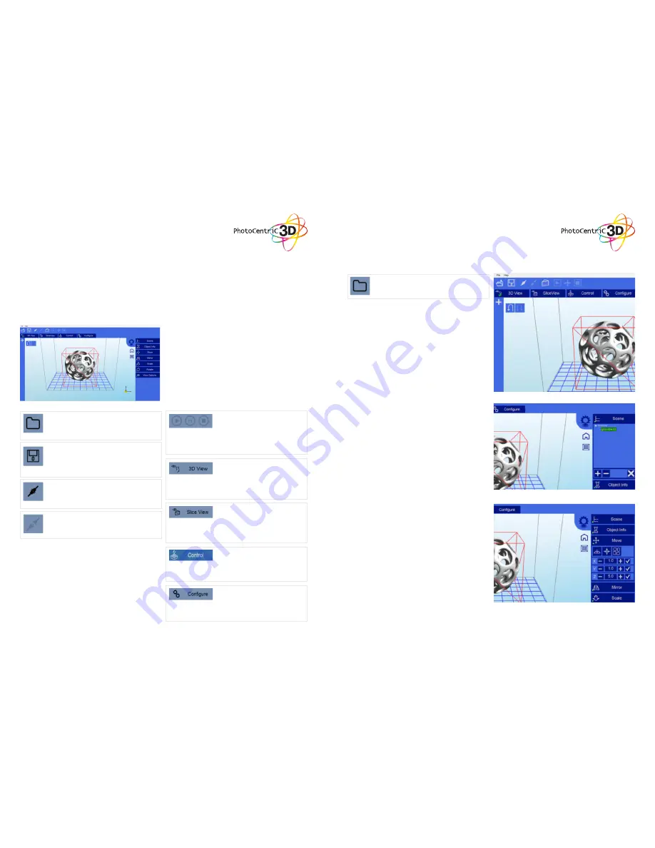
Main screen
Click to open files in one of the following formats:
.STL, .OBJ, .3DS or .AMF. You can also open
scene files with the .CWS extension.
Click this button to disconnect your printer
from the computer. If the button is greyed
out, it means that the machine is currently
disconnected.
Click to save the current object as a .STL or
.CWS file. The .CWS format allows you to prepare
a scene to be printed repeatedly in the future,
together with supports and positioning.
These three buttons start, pause and stop a print.
These buttons only become active once you have
sliced your object.
Clicking this button allows you to view the 3D
objects within their boundary box. You can add
supports in this function.
Clicking this button accesses the “Slicing” screen.
You can see the individual slices that have been
generated as well as the G-code.
This allows you to control the z axis motor, home
it and lift it after a print has finished.
This is the setup screen that allows you to
configure the slicing and printing profiles.
Click to start the connection between your
computer and your Liquid Crystal 3d printer.
Once the button is greyed out, this means that the
printer is connected.
18
1. Loading a Model
The Scene View allows you to manipulate various
aspects of the scene.
Selecting
You can select a model by double clicking on the
model, or selecting it with the scene view
Removing a Model
You can remove a model by right-clicking on the
name in the scene graph and selecting “Remove”.
The Minus sign “-” will also remove the current
model. You can also delete a model by selecting
it and then pressing the “delete” key on your
keyboard.
Cloning a model
You can select a model in the scene and click the
“+” sign to clone it. The cloned object will appear
2. Scene View
Click here to ‘Load’ your file. Multiple objects
can be loaded and manipulated independently.
You can also open scene files with the .CWS
extension.
3. Object Info
4. Move View
The Move function allows you to move objects
on the build platform along the x:y:z axis by the
distance entered.
From left to right, the other tools are:
The ‘Place on Platform’ button will position the
bottom of the model to rest on the bottom of the
build platform.
The ‘Center’ button will center the model at (0,0,0).
• Auto-Arrange will automatically lay out all
models to fit on the build platform. Any model
that does not fit within the build platform will be
moved outside the build area.
This tabs provides you with information about your
model


