19
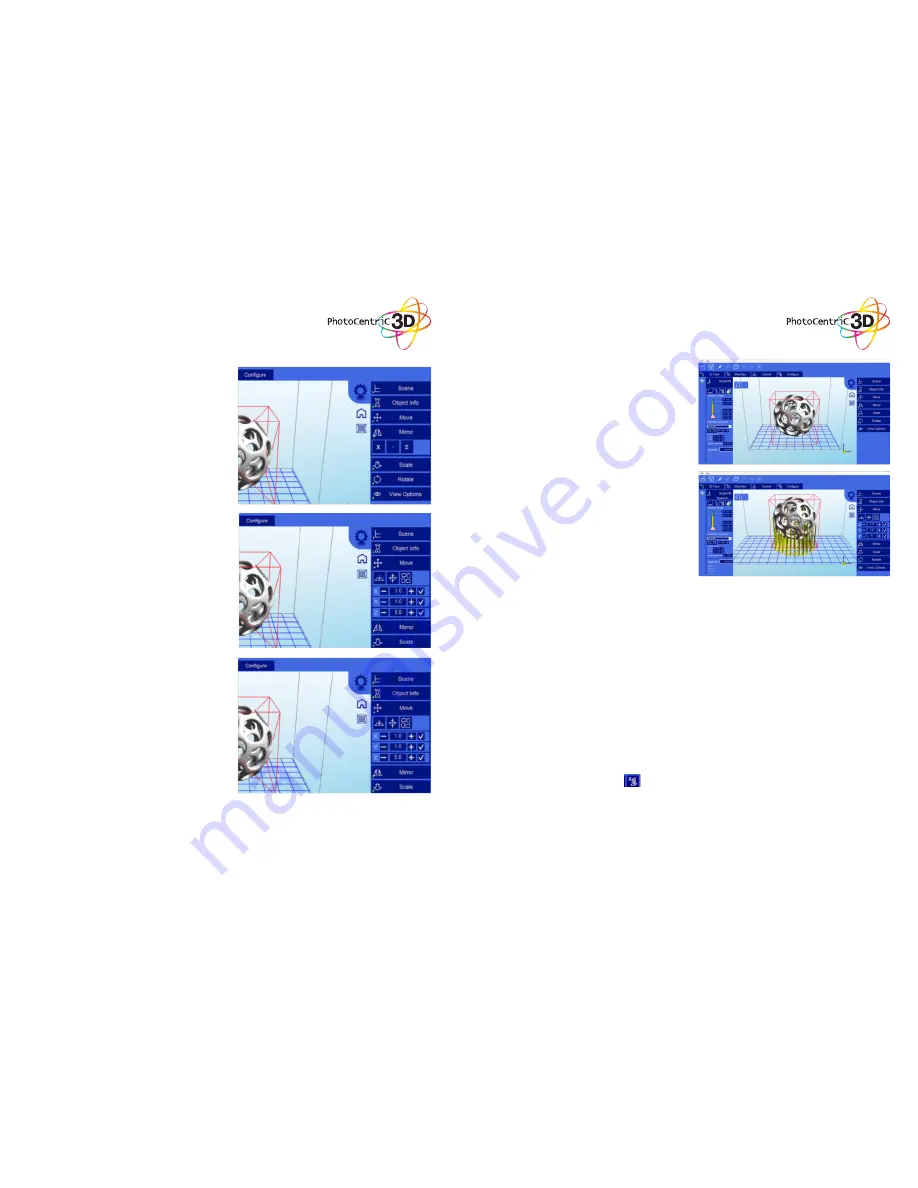
A model can be scaled (reduced or increased) by
selecting it, and using the ‘Scale’ view to enter in a
new scaler value. Press the tick button to re-scale
your object.
6. Scaling objects
7. Rotating Objects
8. View Options
Rotating a model works in a similar way to moving
a model. Simply select the model you want to
work with, and use the X/Y/Z +/- buttons to rotate
the model by your specified degrees.
The view option allows you to manipulate various
views and models.
On the top row from left to right:
• 50% Alpha-Blending toggle. This will allow
you to see through the objects in the scene to
see the geometry
• Show Slice Preview on Scene. After slicing
this toggles on/off the view of the 3D view
of the current slice layer as selected by the
horizontal scrollbar.
• Show Console. This toggle button shows or
hides the debug window. This window is used
for debugging purposes.
On the bottom row from left to right are tools
to change the way the objects appear on the
screen:
• Show objects with a bounding box.
• Show objects with an outline
• Show selected objects in a different color
The Mirror view allows you to mirror the selected
object on the specified axis.
5. Mirroring Objects
20
9. Working with Model Support tools
Using Supports
Supports are sometime required to properly attach
a model to the build space. Because of the nature
of DPP the lower layers must be supported by the
supports unless it has a wide surface in the first
layers. We recommend checking no supports pass
through your object. If they do, you can delete them
and manually add others if needed.
Adding a single Support
A single support can be generated by clicking the
manual support button.
Moving Supports
After a manual or automatic support has been
generated, individual supports can be moved
around the x:y plane the same way models can
be moved. Select the support by double clicking
on it to select it, and hold down the ‘Shift’ key on
your keyboard and move the mouse. Supports will
automatically scale vertically under the model they
support.
Angled Supports
Supports can be angled inwards towards the objects
they support. This can often resolve clearance
issues with vertical supports. You can turn a vertical
support into an angled support by selecting it, and
holding the ‘Ctrl’ key and clicking on the model you
want to support.
Manual Configuration
Under the Support Generation view, you can click
‘show downward facing polys’. This will highlight all
polygons in the model that are pointed downward
by the specified degree. This helps you manually
place supports under un-supported downward
facing areas of a model.
Auto Support on Grid
After a model is loaded into the scene and selected,
you can automatically generate a ‘bed of nails’
support for the model by selecting .
You can specify the grid spacing and the size of the
generated supports. If you wish to only generate
supports on downward facing polygons, check the
boxes under ‘support general’ and ‘generate only
on downward’
Adaptive supports
You can add supports to areas in the model that
are unsupported. There are 2 algorithms to help
you accomplish this.


