background image

page 10

                   POWERPOD User's Manual 

PHONIC CORPORATION

that is sent to the EFX output, which can be used in 

conjunction with external signal processors (this signal 

of which can be returned to mixer via the stereo return 

inputs), or simply as additional auxiliary outputs for any 

means required.  These controls also adjust the level of 

audio that is sent to the built-in digital effect panel.

21. PAN/BAL Control 

      (Powerpods 1060 and 1062 Deluxe only)

This alternates the degree or level of audio that the left 

and right side of the main mix should receive. On mono 

channels, this control will adjust the level that the left 

and right should receive, where as on a stereo channel, 

adjusting the BAL control will attenuate the left or right 

audio signals accordingly.

22. Channel Level Control

This control will alter the signal level that is sent from the 

corresponding channel to the Main mixing bus.

23. PAD -25 Button

The PAD -25 button, located above the 1/4” Phone Jack 

of mono channels, is used to attenuate the input signal 

by 25 dB. This should only be pushed in when using line-

level input devices.

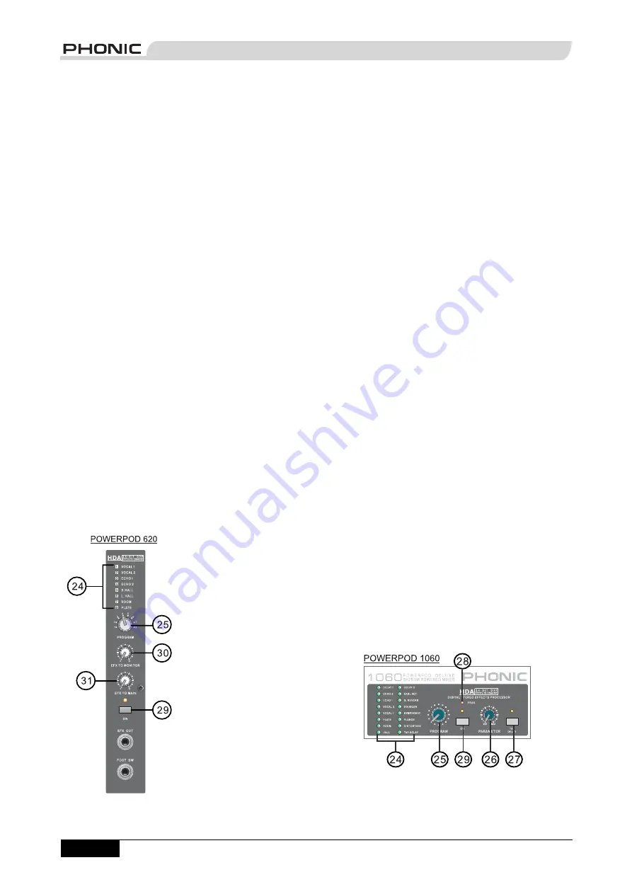
Digital Effect Processor

24. Digital Effect Display

This panel displays the titles of different effects that can 

be added to audio. When 

you select the effect, the 

LED by the effect name will 

illuminate (on the Powerpod 

620 Deluxe the effect 

number is simply selected 

by using the Program Control 

- no LED indicators required), 

and the alteration be applied 

automatically.  For a list of 

available effects, please 

observe the Digital Effect 

Table.

25. Program Control

This control is used to scroll 

through the various effects 

shown on the Digital Effect Display. Turning the control 

will automatically change the effect and apply it to the 

mix.  To see the list of available programs, please check 

the Digital Effect Table.

26. Parameter Control

      (Powerpods 1060 and 1062 Deluxe only)

This will adjust the one main parameter of the digital 

effect that is currently applied to the audio feed. Please 

refer to the Digital Effects Table for more information on 

Effect parameters.

27. Tap Delay Button and Indicator 

      (Powerpods 1060 and 1062 Deluxe only)

When the tap delay effect is selected, this button is used 

to determine the delay time.  By pushing the button 

several times, the mixer interprets the time between 

last two pushes and remembers this as the delay time 

until the button is pushed again; even after the power 

is turned off.  When the tap delay effect is selected, the 

corresponding LED will fl ash at the intervals selected.  

The delay time can also be determined through use of 

a foot switch.

28. Peak Indicator 

      (Powerpods 1060 and 1062 Deluxe only)

This LED indicator will illuminate when the Digital Effect 

Processor overloads.  It is best to adjust the DSP Effect 

Fader so as to ensure the PEAK indicator does not light 

up.  This will ensure a greater quality of audio.

29. Effect On Button and Indicator

This button is pushed to turn the corresponding effect 

panel on or off.  When the effect processor is turned on, 

the corresponding LED illuminates.

Master Section

Summary of Contents for POWERPOD 1060

Page 1: ...vans Limited secure online store at www DeafEquipment co uk DeafEquipment co uk Solutions to improve the quality of life S So ol lu ut ti io on ns s t to o i im mp pr ro ov ve e t th he e q qu ua al l...

Page 2: ...DELUXE POWERED MIXERS POWERPOD 620 740 1060 1062 V1 3 2004 6 29...

Page 3: ...manufacturer or sold with the apparatus When a cart is used use caution when moving the cart apparatus combination to avoid injury from tip over 13 Unplug this apparatus during lighting storms or whe...

Page 4: ...E POWERED MIXERS POWERPOD 620 740 1060 1062 INTRODUCTION 4 FEATURES 4 BASIC SETUP 5 MAKING CONNECTIONS 6 CONTROLS AND SETTINGS 9 APPLICATION 14 DIGITAL EFFECT TABLES 16 SPECIFICATIONS 18 DIMENSIONS 21...

Page 5: ...s and electric guitars or basses 2 built in limiters 2 band channel EQ Pad control on channel 1 4 Monitor and effect sends on each input channel 1 Aux input 48V phantom power Record output with trim c...

Page 6: ...stop making the audio signal 4 You should now select the next channel to set and go back to follow steps 1 through 3 matching Handy mini stereo I O for MD MP3 player recorder input with level control...

Page 7: ...eatured on these outputs to accommodate for devices with different recording levels MAKING CONNECTIONS Channel Inputs The Powerpod 620 740 1060 and 1062 Deluxe Box Mixers supply various numbers input...

Page 8: ...d the inserted feed will be amplified and sent to the Speaker Outputs instead 6 AUX Inputs These TS inputs which are mono inputs on the Powerpods 620 and 740 Deluxe stereo inputs on the Powerpods 1060...

Page 9: ...a loading between 8 and 16 ohms Refer to the Speaker set up chart to the right for a more detailed indication of how to connect speakers NB Due to the fact that the signal has been processed by the po...

Page 10: ...unsure of local voltage levels contact a knowledgeable source before using this mixer Channel Controls 16 HIGH High Frequency Control This control is used to give a shelving boost or cut of 15 dB to...

Page 11: ...alteration be applied automatically For a list of available effects please observe the Digital Effect Table 25 Program Control This control is used to scroll through the various effects shown on the D...

Page 12: ...1062 Deluxe on the other hand feature 2 Tape in controls One that adjusts the final level that is sent to the Monitor mixing bus the upper control another that controls the final level that is sent to...

Page 13: ...activates 48V of Phantom Power for all XLR jacks of all channels on the Powerpod Mixers allowing condenser microphones to be used on these channels The corresponding LED will illuminate when the Mast...

Page 14: ...use of audio while still maintaining fantastic clarity The 620 Deluxe features a single dual 5 segment LED display the 740 Deluxe features a two single 5 segment LED displays for monitor and main sign...

Page 15: ...page 14 POWERPOD User s Manual PHONIC CORPORATION APPLICATION Powerpod 620...

Page 16: ...page 15 PHONIC CORPORATION POWERPOD User s Manual Powerpod 1060...

Page 17: ...for Echo and Reverb of vocals VOCAL 2 Ideal for Echo and Reverb of vocals VOCAL 3 Ideal for Echo and Reverb of vocals ECHO 1 Ideal for Echoing vocals ECHO 2 Ideal for Echoing vocals S HALL Ideal for...

Page 18: ...ms ECHO 2 Ideal for Echoing vocals Delay Time 0 800 ms DELAY 1 Delays the audio signal Delay Time 0 800 ms DELAY 2 Delays the audio signal Delay Time 0 800 ms EARLY REF Modifies early reflections cre...

Page 19: ...send 1 x 1 4 TS Unbal 1 x 1 4 TS Unbal 1 x 1 4 TS Unbal 1 x 1 4 TS Unbal REC out A Pair RCA Mini Stereo A Pair RCA Mini Stereo A Pair RCA Mini Stereo A Pair RCA Mini Stereo Speaker outputs 5 x 1 4 TS...

Page 20: ...Gain at maximum 80 dB 80 dB 80 dB 80 dB Crosstalk 1KHz 0dBu 20Hz to 20KHz bandwidth channel in to main L R outputs Channel fader down other channels at unity 63 dB 63 dB 63 dB 63 dB Channel muted othe...

Page 21: ...igital effect mute ON OFF Digital effect mute ON OFF Digital effect mute ON OFF Microphone Preamp E I N 150 ohms terminated max gain 122 dBm 122 dBm 122 dBm 122 dBm Power Consumption Average Maximum 1...

Page 22: ...471 mm 18 5 inches 471 mm 18 5 inches 471 mm 18 5 inches B 245 mm 9 6 inches 265 mm 10 4 inches 285 mm 11 2 inches 285 mm 11 2 inches C 275 mm 10 8 inches 275 mm 10 8 inches 275 mm 10 8 inches 275 mm...

Page 23: ...1 M ONI TOR B FOO T SW LOW Z EFF ECT 7K HA TO M ONI TOR HI GH EFF ECT OUT EQ LOW Z LIN E2 EFF ECT A M INI STEREO PA2 M AIN OUT SUPER HI Z Pr ogram M ASTER M ON DI SPLAY DI SPLAY LOW TO M AIN SUM TAPE...

Page 24: ...page 23 PHONIC CORPORATION POWERPOD User s Manual POWERPOD 740 BLOCK DIAGRAM...

Page 25: ...page 24 POWERPOD User s Manual PHONIC CORPORATION POWERPOD 1060 BLOCK DIAGRAM...

Page 26: ...P RO G R AM MA I N O U T LEVEL HI G H R Lo Z TO M O N LEVEL R EQ I N H A SPK_R A R I G H T EFX SU P E R H i Z R D I SPLAY M O N LEVEL MA I N LEVEL TO N E L D I SPLAY LOW LEVEL R EC O U T LOW M O N 10...

Page 27: ......

Reviews: