background image

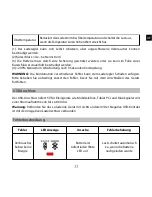
Übertemperatur  Reduziert den Ladestrom bei Übertemperatur und schaltet die Last aus, 

wenn die Temperatur einen hohen Wert erreicht hat. 

(1)  Der   Laderegler   kann   sich   selbst   schützen,   aber   angeschlossene   Verbraucher   können 

beschädigt werden. 

(2) Kurzschluss: >4x – 6x Nennstrom. 

(3)  Die Batterie muss durch eine Sicherung geschützt werden, oder sie kann im Falle eines 

Kurzschlusses dauerhaft beschädigt werden. 

(4) >200% Nennstrom: Abschaltung nach 3 Sekunden Verzögerung 

WARNUNG:

  Die Kombination verschiedener Fehler kann dem Laderegler Schaden zufügen. 

Bitte beheben Sie unbedingt zuerst den Fehler, bevor Sie mit dem Anschließen des Geräts  

fortfahren. 


USB Anschluss

Der USB-Anschluss liefert 5 V für Kleingeräte wie Mobiltelefone, Tablet PCs und Musikspieler mit 

einer Stromaufnahme von bis zu 800 mA.

Warnung:

 Verbinden Sie das zu ladende Gerät mit nichts anderem! Der Negative USB-Kontakt 

ist mit dem negativen Lastanschluss verbunden.


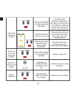
Fehlerbeschreibung

Fehler 

LED Anzeige 

Ursache 

Fehlerbehebung 

Verbraucher 

haben keine 

Energie 

Batterie ist 

tiefentladen (Rote 

LED an) 

Last schaltet automatisch 

zu, wenn die Batterie 

nachgeladen wurde 

11

DE

Summary of Contents for CMLup

Page 1: ...Phocos CMLup Solar charge controller Bedienungsanleitung User Manual Manual del usuario Manuel de l utilisateur Manual de Usu rio CID 181815611...

Page 2: ...CONTENTS Bedienungsanleitung User Manual Manual de Instrucciones Guide de l utilisateur Manual do Usu rio 1 16 17 31 32 46 47 62 63 78 79 93...

Page 3: ...Ger ten Max 16 mm2 Anschlussklemmen 10 mm2 Litze mit Aderendh lse Vollst ndiger elektronischer Schutz WICHTIGE ALLGEMEINE SICHERHEITSHINWEISE BITTE BEWAHREN SIE DIESE ANWEISUNGEN AUF Dieses Handbuch...

Page 4: ...urch lose oder schlechte Verbindungen eine Hitzeentwicklung zu verursachen Bitte schlie en Sie zuerst eine Sicherung oder einen Unterbrecher in der N he der Batterie an bevor Sie den Laderegler einste...

Page 5: ...er ume montiert werden Der Laderegler misst zur Bestimmung der Ladespannung die Temperatur Laderegler und Batterie m ssen im selben Raum untergebracht werden Da sich der Regler im Betrieb erw rmen kan...

Page 6: ...das Ger t in ein Fahrzeug eingebaut werden dessen Batterie Minus an der Masse liegt so d rfen am Regler angeschlossene Verbraucher und das Modul keinesfalls mit der Fahrzeug Masse verbunden sein da d...

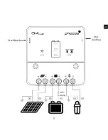
Page 7: ...5 Steckbr cken USB Anschluss DE Sich erung...

Page 8: ...ektrolyt verwenden k nnen Sie die Ladecharakteristik einstellen siehe auch Einstellungen Es wird dann die Ausgleichsladung aktiviert Bei Unklarheiten ber die erforderlichen Einstellungen wenden Sie si...

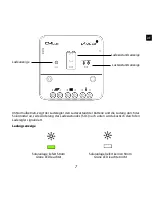
Page 9: ...adung durch das Solarmodul an Jede nderung des Ladezustandes SOC nach unten wird akustisch durch den Laderegler signalisiert Ladungsanzeige Solaranlage liefert Strom Solaranlage liefert keinen Strom G...

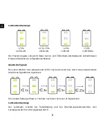
Page 10: ...vollgeladenen Batterie Akustische Signale Bei einem Wechsel des Ladezustandes SOC nach unten wird dies durch eine entsprechende Anzahl von Signalt nen signalisiert Die Lastabschaltung erfolgt ca 1 Mi...

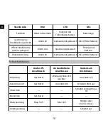
Page 11: ...Eigenschaften 2 Spannungsgesteuert Abschaltung 11 0 V 22 0 V fix geeignet falls Verbraucher direkt an die Batterie angeschlossen sind und der Laderegler nicht den gesamten Laststrom erfassen kann Werk...

Page 12: ...t Fl ssigs ure Batterie Werkseinstellung Alarm An Ladezustandsgesteuert GEL VRLA Batterie Schutzfunktionen An den PV Anschl ssen An den Batterie Anschl ssen An den Last Anschl ssen Verpolung Gesch tzt...

Page 13: ...Die Kombination verschiedener Fehler kann dem Laderegler Schaden zuf gen Bitte beheben Sie unbedingt zuerst den Fehler bevor Sie mit dem Anschlie en des Ger ts fortfahren USB Anschluss Der USB Anschlu...

Page 14: ...Falls nicht ist der Laderegler defekt Batteriezuleitung oder Batteriesicherung defekt Batterie hochohmig Bitte berpr fen Sie die Batteriezuleitungen Sicherungen und die Batterie Batterie ist nach kurz...

Page 15: ...8 27 6 V 25 C Spannung Hauptladung 14 4 28 8 V 25 C 0 5 Std t glich Boost Ladung 14 4 28 8 V 25 C 2 Std Aktivierung Batteriespannung 12 3 24 6 V Ausgleichsladung 14 8 29 6 V 25 C 2 Std Aktivierung Ba...

Page 16: ...maufnahme 5 mA Erdung Positiv Erdung Umgebungstemperatur 40 bis 50 C Max H he 4 000 m NN Batterietyp Blei GEL AGM Fl ssigs ure USB Anschluss 5 0 V 800 mA Abmessungen BxHxT 100 x 100 x 28 mm Gewicht 13...

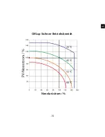
Page 17: ...15 CMLup Sicherer Betriebsbereich Nennlaststrom DE...

Page 18: ...es Batterieherstellers missachtet werden Der Hersteller haftet nicht wenn Reparaturen oder Kundendienst von nicht autorisierten Personen durchgef hrt wurden bei unsachgem sser Gebrauch falscher Instal...

Page 19: ...end sleves Complete electronic protection IMPORTANT SAFETY INSTRUCTIONS SAVE THESE INSTRUCTIONS This manual contains important instructions for CMLup controller that shall be followed during installa...

Page 20: ...voltage risks Operation of this device may produce high voltages which can cause severe injuries or death in case of improper installation or operation of the device PV modules can generate high DC v...

Page 21: ...ler then to the battery and to the photovoltaic modules But for the load first connect the wire to the load then to the controller Recommended minimum wire size CMLup 10 4 mm2 CMLup 20 6 mm2 Make sure...

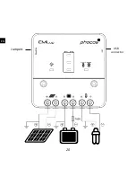
Page 22: ...20 EN USB connector Jumpers...

Page 23: ...to operate with lead acid batteries with solid electrolyte GEL type or AGM type If you intend to use a lead acid battery with liquid electrolyte you can adjust the charging characteristics see Settin...

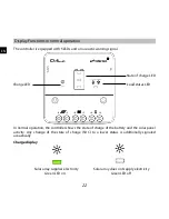
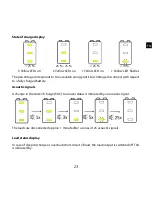
Page 24: ...oller shows the state of charge of the battery and the solar panel activity Any change of the state of charge SOC to a lower status is additionally signaled acoustically Charge display Solar array sup...

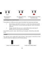
Page 25: ...Disconnect with respect to a fully charged battery Acoustic signals A change in the state of charge SOC to a lower status is indicated by an acoustic signal The loads are disconnected approx 1 minute...

Page 26: ...23 8 V at no load current Normal operation mode for safe battery protection 2 Voltage controlled Disconnect at 11 0 V 22 0 V fixed setting Appropriate if bypass loads draw current directly from the ba...

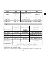
Page 27: ...g Red LED on Protected 1 Short circuit 2 Protected Protected 3 Switches off immediately Over current Switches off with a delay 4 Reverse current Protected Over voltage Max 50 V Max 50 V Switches off a...

Page 28: ...ct portable computers small music players with up to 800 mA of current consumption Warning Do not connect the charging device anywhere else USB negative contact is connected to load negative Error Des...

Page 29: ...gh resistance Check battery wires fuses and battery Battery is empty after a short time Battery shows low capacity Red LED on Change battery Battery is not being charged during the day Solar array fau...

Page 30: ...5 C Main charge 14 4 28 8 V 25 C 0 5 h daily Boost charge 14 4 28 8 V 25 C 2 h Activation battery voltage 12 3 24 6 V Equalization 14 8 29 6 V 25 C 2 h Activation battery voltage 12 1 24 2 V at least...

Page 31: ...Positive grounding Ambient temperature 40 to 50 C Max altitude 4 000 m above sea level Battery type Lead acid GEL AGM flooded USB connector 5 0 V 800 mA Dimensions WXHXD 100 x 100 x 28 mm Weight 130 g...

Page 32: ...30 EN CMLup Safe Operating Area SOA...

Page 33: ...ations of the battery manufacturer are neglected The manufacturer shall not be liable if there has been service or repair carried out by any unauthorized person unusual use wrong installation or bad s...

Page 34: ...mangas en los extremos del cable Protecci n electr nica completa INSTRUCCIONES DE SEGURIDAD IMPORTANTES GUARDE ESTAS INSTRUCCIONES Este manual contiene instrucciones importantes para el controlador CM...

Page 35: ...Instale y utilice el controlador en un ambiente seco Riesgos de alto voltaje La utilizaci n de este equipo puede producir un alto voltaje que podr a provocar lesiones graves o la muerte en caso de un...

Page 36: ...sumo al controlador de carga polo positivo y polo negativo Siga el procedimiento inverso a la hora de desinstalar el sistema Para evitar voltaje en el cableado conecte en primer lugar el cable al cont...

Page 37: ...35 Puentes Conector USB ES Fusible...

Page 38: ...ndido el voltaje de la bater a no est dentro de la escala normal de funcionamiento se muestra un MENSAJE DE ERROR Tipo de bater a El controlador est programado para funcionar con bater as de plomo con...

Page 39: ...arga de la bater a y la carga de los paneles solares Cualquier descenso del estado de la carga SOC se se ala adem s ac sticamente Visualizaci n de la carga Visualizaci n de la carga El m dulo solar su...

Page 40: ...bater a cargada completamente y el m nimo indicado con Desconexi n por Bajo Voltaje Se ales ac sticas El descenso del estado de la carga SOC se indica mediante una se al ac stica Se desconectan los c...

Page 41: ...orriente Modo de funcionamiento normal para una buena protecci n de la bater a 2 Voltaje controlado Desconecta en el par metro fijo de 11 5 V 23 0 V Apropiado si otros consumos retiran corriente direc...

Page 42: ...je controlado Bater a inundada Ajuste de factor a Alarma activada Estado de carga controlado GEL bater a VRLA Caracter sticas de Seguridad Bornes FV Bornes de la bater a Bornes de consumo Polaridad in...

Page 43: ...erentes circunstancias de error puede da ar el controlador Corrija siempre un error antes de proseguir con la conexi n del controlador Conector USB Conector USB para suministro de energ a de 5V para p...

Page 44: ...tras fuentes no est n sobrecargando la bater a De otro modo se da ar el controlador Los cables o el fusible de la bater a est n da ados la bater a tiene una resistencia elveada Compruebe los cables y...

Page 45: ...20 Voltaje del sistema 12 24 V autoreconocimiento Corriente de carga m x 10 A 20 A Corriente de consumo m x 10 A 20 A Carga de flotaci n 13 8 27 6 V 25 C Carga principal 14 4 28 8 V 25 C 0 5 h diaria...

Page 46: ...emperatura Voltage carga 4 2 mV K por c lula Autoconsumo idle 5 mA Toma de tierra Positive aterrisado Temperatura ambiente 40 a 50 C Altitud m x 4 000 m sobre el nivel del mar Tipo de bater a Plomo GE...

Page 47: ...45 Corriente consumo nominal ES Area de seguridad SOA del CMLup...

Page 48: ...an las recomendaciones del fabricante de la bater a El fabricante no se hace responsable si se han llevado a cabo reparaciones a cargo de personal no autorizado o por un uso inusual una mala instalaci...

Page 49: ...ection lectronique totale CONSIGNES DE S CURIT IMPORTANTES CONSERVEZ CES INSTRUCTIONS Ce manuel contient des instructions importantes pour installation operation maintenance du r gulateur de charge so...

Page 50: ...avant d installer ou r gler l appareil Le r gulateur doit tre install et utilis uniquement dans un endroit sec Risques li s la haute tension Le fonctionnement du r gulateur de charge peut g n rer une...

Page 51: ...t les polarit s et 2 Raccordez les panneaux photovolta ques au r gulateur de charge en respectant les polarit s et 3 Raccordez les charges au r gulateur de charge en respectant les polarit s et Pour d...

Page 52: ...50 Cavaliers Port USB FR Fusible...

Page 53: ...ent normal Tension du syst me Le r gulateur de charge s ajuste automatiquement la tension du syst me en 12 V ou 24 V D s que la tension d passe 18 0 V au d marrage le r gulateur passe automatiquement...

Page 54: ...son chargement Ceci est garder en m moire en particulier si vous installez des charges suppl mentaires Fonctions d affichage en cours de fonctionnement normal Le r gulateur de charge est quip de 5 LED...

Page 55: ...ge de l tat de charge 75 25 75 25 10 3 LED 2 LED 1 LED 1 LED jaunes allum es jaunes allum es jaune allum e jaune clignote Les pourcentages correspondent l nergie disponible jusqu la d connexion basse...

Page 56: ...on basse tension Surcharge ou court circuit de la charge LED rouge teinte LED rouge allum e LED rouge clignote Fonction de d connexion basse tension Le r gulateur dispose de 2 modes diff rents pour vi...

Page 57: ...valiers sur le c t gauche du r gulateur permettent de proc der aux r glages suivants Cavalier ferm cavalier connect Cavalier ouvert cavalier d connect Cavalier BUZ LVD GEL Fonction Signal sonore Fonct...

Page 58: ...arge en cas de surchauffe et extinction des charges si la temp rature atteint un niveau lev 1 Le r gulateur est quip d un dispositif d autoprotection mais les charges branch es peuvent tre endommag es...

Page 59: ...sur d autres bornes Le contact n gatif du port USB est connect la borne n gative de la charge Description des erreurs Erreur Affichage Cause Solution Les charges ne sont pas aliment es La batterie es...

Page 60: ...la batterie les fusibles et la batterie La batterie se d charge apr s une br ve p riode La capacit de la batterie est faible LED rouge allum e Changer la batterie La batterie ne se recharge pas au co...

Page 61: ...8 27 6 V 25 C Charge principale 14 4 28 8 V 25 C 0 5 h par jour Charge forc e 14 4 V 28 8 V 25 C 2h Activation tension de la batterie 12 3 V 24 6 V galisation 14 8 V 29 6 V 25 C 2h Activation tension...

Page 62: ...rre Mise la terre positive Temp rature ambiante 40 50 C Altitude maximale 4000 m au dessus du niveau de la mer Type de batterie Plomb acide GEL AGM ouverte Port USB 5 0 V 800 mA Dimensions l x h x p 1...

Page 63: ...61 Courant nominal charge FR Aire de s curit SOA du CMLup...

Page 64: ...n ont pas t respect es Le fabricant ne peut tre tenu pour responsable si des op rations de maintenance ou de r paration ont t effectu es par des personnes non autoris es des utilisations inhabituelle...

Page 65: ...onex o para condutores com at 16 mm cabo flex vel com luva at 10 mm2 Prote o eletr nica completa INSTRU ES DE SEGURAN A IMPORTANTES ACONSELITAMOS GUARDAR ESTE MANUAL Este manual cont m recomenda es im...

Page 66: ...imo bateria antes de iniciar a instala o ou ajustes do controlador Instale e utilize o controlador em lugar seco Perigo de tens o elevada A utiliza o deste dispositivo pode produzir tens es elevadas o...

Page 67: ...e negativo 3 Conecte a carga consumidor ao controlador positivo e negativo Siga o procedimento inverso caso necessite desinstalar Para evitar qualquer tens o indesejada nos condutores conecte primeir...

Page 68: ...66 Jumpers Conector USB PO Fus vel...

Page 69: ...tens o do sistema 12 V ou 24 V Sistemas com tens o 18 V S o reconhecidos como sistemas 24 V Caso a tens o da bateria n o se encontre dentro dos limites esperados o controlador exibir a indica o de fa...

Page 70: ...is Sinaliza o por LED em opera o normal O controlador est equipado com 5 LEDs e um sinalizador ac stico Gera o Durante opera o normal o controlador mostra o estado de carga da bateria e da energia rec...

Page 71: ...10 3 LEDs amarelos ligados 2 LEDs amarelos ligados 1 LED amarelo ligado 1 LED amarelo piscando Percentagem correspondente energia dispon vel em rela o bateria completamente carregada at chegar ao est...

Page 72: ...Desconex o baixa tens o Sobrecarga ou curto circuito terminal carga LED vermelho desligado LED vermelho ligado LED vermelho piscando Fun o Desconex o por Baixa Tens o LVD O controlador de carga possu...

Page 73: ...ura es O controlador de cargas pode tamb m ser configurado para condi es de opera o espec ficas Tr s Jumpers do lado esquerdo do controlador poder o ser feitos os seguintes ajustes Jumper inserido Sem...

Page 74: ...Sobreaquecimen to Reduz a corrente de carga em caso de sobreaquecimento e desconecta a carga na temperatura limite 1 O controlador de cargas se autoprotege consumidores poder o todavia ser danificados...

Page 75: ...o el trico do sistema O contato negativo do conector USB est diretamente conectado ao polo negativo da bateria Sinaliza es de falha Sinaliza o LED Causa Solu o N o h energia Bateria com baixa carga LE...

Page 76: ...a bateria est o danificados bateria com resist ncia interna elevada Verifique os condutores e fus veis da bateria e tamb m a bateria propriamente dita Vida reduzida da bateria Baixa Capacidade da bate...

Page 77: ...de sistema 12 24 V reconhecimento autom tico M xima corrente de carga 10 A 20 A M xima corrente de consumo 10 A 20 A Tens o de flutua o 13 8 27 6 V 25 C N vel de tens o carga principal 14 4 28 8 V 25...

Page 78: ...Prote o contra sub tens o 10 5 21 0 V Tens o m xima de painel 50 V Tens o m xima de bateria 50 V Compensa o de temperatura Tens o de carga 4 2 mV K por c lula da bateria Autoconsumo repouso 5 mA Cond...

Page 79: ...Grau de prote o tipo IP20 Vide gr fico da SOA rea de prote o segura 77 Corrente nominal consumidor PO CMLup SOA...

Page 80: ...das recomenda es feitas pelo fabricante da bateria O fabricante n o se responsabiliza pelos servi os ou reparos efetuados por pessoas n o autorizadas uso indevido instala o incorreta ou mal desempenh...

Page 81: ...CMLup USB MP3 16 10 CMLup 0 5m GEL AGM 12 24 V 1 5 79 CH...

Page 82: ...CE CE 12 V 24 V 80 CH...

Page 83: ...1 2 3 CMLup 10 4 mm2 CMLup 20 6 mm2 CMLup 1 5 CMLup 10 15 A CMLup 20 30 A 81 CH...

Page 84: ...82 USB CH...

Page 85: ...12 V 24 V 18 V 24 V 5 LED 83 CH...

Page 86: ...LED LED 84 CH...

Page 87: ...75 25 75 25 10 3 LED 2 LED 1 LED 1 LED 25 1 85 CH...

Page 88: ...LED LED LED CML 1 SOC 11 4 22 8 V 11 9 23 8 V 2 LVD 11 0 22 0 V 1 86 CH...

Page 89: ...BUZ LVD GEL LED 1 2 3 4 50 V 50 V 15 5 31 0V 1 2 4 6 87 CH...

Page 90: ...3 4 200 3 s USB USB 5 V 800 mA USB LED LED 88 CH...

Page 91: ...15 5 31 0 V LED LED LED 89 CH...

Page 92: ...20 12 24 V 10 A 20 A 10 A 20 A 13 8 27 6 V 25 C 14 4 28 8 V 25 C 0 5 h 14 4 28 8 V 25 C 2 h 12 3 24 6 V 14 8 29 6 V 25 C 2 h 12 1 24 2 V 30 15 5 31 0 V 11 4 11 9 22 8 23 8 V 11 0 22 0 V 12 8 25 6 V 10...

Page 93: ...4 2 mV K per cell 5 mA 40 50 C 4 000 AGM USB 5 0 V 800 mA WXHXD 100 x 100 x 28 mm 130 g 16 mm IP20 91 CH...

Page 94: ...92 CMLup SOA CH...

Page 95: ...20140708 Phocos AG Germany www phocos com 93 ISO9001 RoHS CH...

Reviews: