


Mechanical Instructions
EN 9
TES1.0E LA
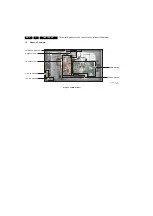
4.
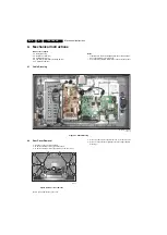
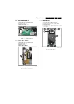
4.3
Subframe Removal
1.
Remove the rear cover, as described above.
2.
Remove fixation screws [1].
3.
Remove the subframe [2].
Figure 4-3 Subframe removal
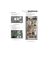
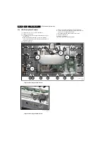
4.4
Main Board Removal
1.
Remove the subframe, as described above.
2.
Unplug connectors [1].
3.
Carefully unplug the fragile LVDS connector [2].
4.
Remove fixation screws [3].
5.
Remove the main board.
Figure 4-4 Main board removal
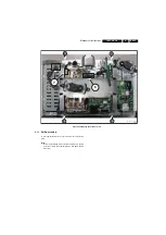
4.5
Power Supply Removal
1.
Remove the subframe, as described above.
2.
Unplug connectors [1] from the power supply.
3.
Remove fixation screws [2].
4.
Remove the power supply.
Figure 4-5 Power supply removal
G_16510_009.ep
s
171106
1
1
2
G_16510_011.ep
s
161106
1
2
3
3
G_16510_01
3
.ep
s
161106
1
2
2
2


