Chenbro RB14604, User Manual
The Chenbro RB14604 is a high-quality server chassis designed for optimal performance and reliability. For easy setup and maintenance, make sure to download the User Manual for free from our website. This comprehensive manual will guide you through the installation and operation of your RB14604 chassis.
Share
Download


Reviews:
No comments
Related manuals for RB14604

PAC-170
Brand: ICP Pages: 19

SC827HD-R1400B
Brand: Supero Pages: 82

A-F5000
Brand: HP Pages: 97

A-F5000
Brand: HP Pages: 145

KCT52A
Brand: Samsung Pages: 93

96864-1
Brand: ADLINK Technology Pages: 64

SC825S2-560LPV
Brand: Supermicro Pages: 72

GT24B-B5542
Brand: TYAN Pages: 74

LS18
Brand: Changhong Electric Pages: 34

CS-RMCPS-14
Brand: CSN Pages: 2
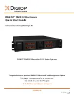
NVR 2U
Brand: Digiop Pages: 4

cDAQ-9171
Brand: National Instruments Pages: 4


