background image

45

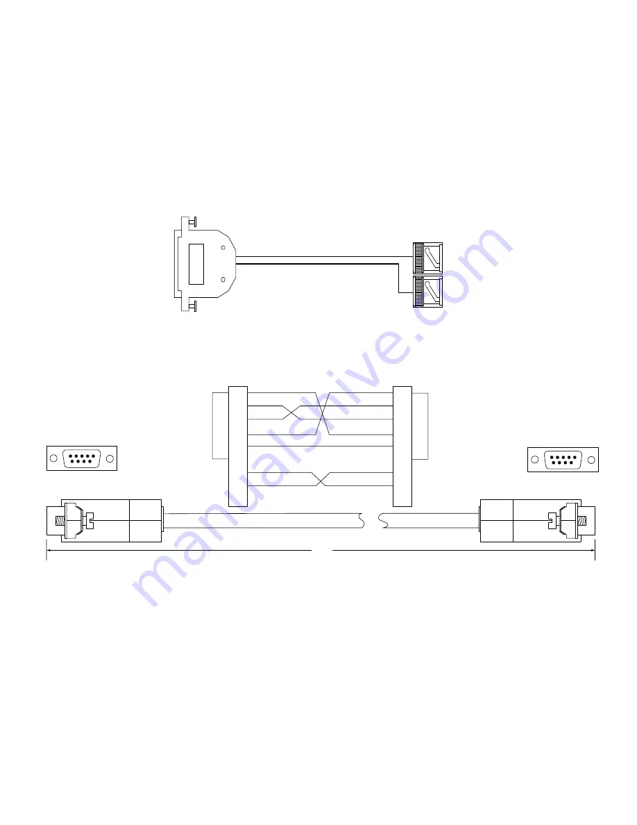
25-pin Male

D-connector

OUT


BNC

Connector

IN 

BNC

Connector

 5     4     3     2     1

9      8      7    6

 5     4     3     2     1

9      8      7    6

System4

 Console Port 

Connector

PC Serial Port

Connector

9-pin Female

9-pin Female

72.0-in

1

2

3

4

5

6

7

8

9

1

2

3

4

5

6

7

8

9

Note: 

Be sure to use a Null Modem Cable.

Figure A3  

System4

Server Interface Cable Specifications

Figure A4  

System4

Console Cable Detail (Part Number S1385)

Summary of Contents for System4 Seriver

Page 1: ...Server Philips Communication Security Imaging Installation Instructions Eng ...

Page 2: ...2 ...

Page 3: ...o dangerous voltage or other hazards Refer all servicing to qualified service personnel 17 Damage Requiring Service Unplug the unit from the outlet and refer servicing to qualified service personnel under the following conditions a When the power supply cord or plug is damaged b If liquid has been spilled or objects have fallen into the unit c If the unit has been exposed to rain or water d If the...

Page 4: ...t d une valeur suffisante pour constituer un risque d électrocution Le point d exclamation contenu dans un triangle équilatéral avertit l utilisateur de la présence dans la documentation qui accompagne l appareil de consignes d utilisation et de maintenance importantes Attention L installation doit être effectuée uniquement par du personnel de service qualifié conformément à la réglementation du C...

Page 5: ...susario de que instrucciones de operación y mantenimiento importantes acompañan al equipo Atención La instalación de este equipo debe ser realizada por personal capacitado solo en acuerdo y en cumplimiento de normas del National Electric Code Código Eléctrico Nacional ó las normas del Gobierno Nacional Local Para Desconectar la Alimentación Unidades no equipadas con interruptores ON OFF son alimen...

Page 6: ...1 Introduction to System4 Server Operation 24 4 2 Viewing Live Video 24 4 3 System4 Server Recording and Scheduling 26 4 4 Searching for and Viewing Recorded Video 30 4 5 Exporting Captured Images and Video 31 4 6 Viewing Disk Usage 32 SECTION 5 System4 REMOTE VIEWER SOFTWARE 33 5 1 Introduction to Remote Viewer Software 33 5 2 Using the Remote Viewer Software 34 SECTION 6 TROUBLESHOOTING 40 APPEN...

Page 7: ...and 10 100 BaseT Ethernet card monitor NOT included System4 Multiplexer model LTC 2682 90 for the System4 Server 32 two 2 Multiplexers are needed System4 Server Instruction Manual this manual System4 Multiplexer Instruction Manual System4 Server Configuration Software System4 Remote Viewer Software on CD ROM Windows Operating system on CD ROM 1 Interface Cable for the System4 Server 32 two 2 Inter...

Page 8: ...ive Size GB 150 240 320 640 320 640 CD RW N A Included Included Included Included Included Alarm Inputs 16 16 16 16 32 32 Alarm Outputs 2 2 2 2 4 4 Network Interface Included RJ 45 Included RJ 45 Included RJ 45 Included RJ 45 Included RJ 45 Included RJ 45 Card Ethernet Remote Viewing Software Included Included Included Included Included Included Rated Voltage 120 230 VAC 120 230 VAC 120 230 VAC 12...

Page 9: ...nector on the rear of the System4 Server PC 4 Plug the IN connector of the System4 Server Interface cable to the VCR OUT connector located on the rear of the multiplexer 5 Connect the OUT connector of the System4 Server Interface cable to an external video monitor VCR or other analog device if you would like to view record exported System4 Server video 6 If images from the System4 Server will be v...

Page 10: ...CR Optional PC Monitor Not Supplied Ethernet Network Port Optional Use Typical Fixed Cameras AC Main Power System4 Console Cable System4 Keyboard Note 1 AC Main Power Keyboard Cable Typical System4 Alarm Input Optional Up to 16 System Cameras Biphase Control Data Video Video Video Video IN Cable Mouse Cable Keyboard Cable AutoDome Series Controllable Camera Dome Camera Note 1 These components are ...

Page 11: ...ptional System4 Mon B Optional System4 Mon B Note 1 System4 Keyboard Note 1 Keyboard Cable AC Main Power Typical System4 Alarm Input Optional Up to 16 System Cameras AutoDome Series Controllable Camera Dome Camera Video Video Video AutoDome Series Controllable Camera Dome Camera Video Video Video Video Typical Fixed Cameras Typical Fixed Cameras Up to 16 System Cameras Typical System4 Alarm Input ...

Page 12: ...K to continue From the desktop you can also start the configuration software program by double clicking the System4 Server icon When the Configuration Software program first begins to run the System4 Remote Viewer software will automatically start on the server and be minimized to the system tray by default To view press the Windows button on the keyboard while the System4 is running and double cl...

Page 13: ...he configuration screen is a status bar that displays information about the current date and time the current status of each camera disk usage and whether the system is currently recording The Function Buttons At the top left corner of the configuration main screen are the Philips logo and the six buttons providing links to the following pages The top left corner where the Philips logo is located ...

Page 14: ...attention to the event The amount of disk space that is full The status of system operation either Live not recording or REC recording 3 2 Setting Up the Configuration Software for System Operation Many important system functions can be configured through the Configuration main screen Setup function button The Setup page which appears after clicking on the Setup button includes 7 tabs which are ex...

Page 15: ... temporarily stores a certain amount of video at all times in case an alarm occurs This requires a reserved amount of storage space The amount of prealarm recording time you can program is limited by the recording rate and image size specified for all cameras set for prealarm recording The amount of memory used is determined by the resolution and record rate selection for each camera The Pre Alarm...

Page 16: ...then represented by an active button at the bottom of the screen even if no camera is actually hooked up to the input 2 You can also have the software search for the new camera by clicking Rescan The window shown below will appear during the scanning process 3 When you disconnect a camera you can either click Rescan or manually deselect the camera input from the Channel Configuration window NOTE T...

Page 17: ...The camera s name is limited to 32 characters if you decide to change it However a relatively long camera name may automatically be abbreviated to fit into certain areas of the Monitor and Schedule pages Setup Tab 3 Configuring Disk Usage To configure which disk drives the system records to go to the Setup page and click the Disk tab ...

Page 18: ...aptured video At the bottom of the Disk tab are two drop down calendars Enter starting and stopping dates All video captured on or between these dates will be deleted Then click the Purge button You can also purge video from all days by selecting Full Purge before you click the Purge button You should see the bar graph change to indicate that a portion of each disk was emptied Note that purging a ...

Page 19: ... level of security only an operator logged in with Administrator permissions can access other areas of the system The top left corner where the Philips logo is located is actually a button to access a version information screen which also contains a Log on button If the software is currently restricted based on the user who is currently logged in an Administrator can press this button to log on an...

Page 20: ...s in the image that need to change for motion to be detected multiplied by 100 For example a Percentage Area setting of 250 2 5 percent means that nine of the blocks 0 025 368 would have to change for motion to be detected The lowest setting you can use is about 30 or 0 3 percent which requires a single block in the image to change from the reference frame for motion to be detected Setting the Per...

Page 21: ...the view screen 3 On the view screen use your mouse to paint the areas of the picture where motion should not be detected a blue box appears wherever you click 4 To erase portions of the mask click on an area with a blue box in it and drag the cursor to wherever the mask should be eliminated 5 To eliminate a motion mask click the Clear Mask button The changes are applied automatically For the mask...

Page 22: ... Alarms 1 through 16 correspond to the alarm inputs located on the rear panel of the respective multiplexer s The drop down list will show all alarms available on the System4 Server If only one multiplexer has been configured for this application the sixteen 16 available alarms are labelled as System4 Server Alarm 1 through System4 Server Alarm 16 If the System4 Server has two 2 multiplexers confi...

Page 23: ...s if a door or window is left open the system will record for only the two minutes 120 seconds and then stop This feature prevents the system from filling the disk with video long after the actual security breach occurs 5 When the alarm is configured properly click the Activate button Alarm Scheduling The Alarms tab allows special scheduling of alarm recording If you leave the Always On checkbox s...

Page 24: ...tain a black number buttons for unused or inactive inputs are grayed out To display the name of the cameras in the video windows click OSD on the Main tab as seen in the following Variable speed Pan Tilt Zoom PTZ control is available Movement is possible by two different methods for the camera that is selected framed in white on the Monitor page The first method is to select the multidirectional a...

Page 25: ...figured 3 3 or in 16 windows configured 4 4 To switch to one of these modes click the appropriate button in the bottom right corner of the screen If there are more camera inputs than available video windows on the Monitor page camera inputs are organized on multiple pages For example in 2 2 mode four windows are displayed at a time To see the remaining camera inputs click the left and right arrows...

Page 26: ... System4 Server Recording and Scheduling There are three types of recording modes On the Schedule page each mode is associated with a color to help you set up and visualize the schedule The following describes the three types of recording modes and their associated colors Alarm red records video only if an alarm is triggered during the time period you specify on the Schedule page The maximum durat...

Page 27: ...k Setup for Simple Schedules The three color coded buttons Motion Alarm and Free in the Select Mode area allow you to quickly set up all of the cameras to record in the same mode To do this click on the appropriate button and then click Set All Cameras If you select the Motion button all of the schedule bars turn blue if you select Alarm all of the bars turn red and so on Even when using the quick...

Page 28: ...ven if you will or have set a default for weekdays and weekends To set a custom schedule perform the following steps 1 On the Schedule page click on the day you want to set the schedule for If the day falls on a month other than the one shown in the calendar use the drop down lists to select a new month and or year or use the Today button and the arrows to navigate the calendar 2 Create schedule b...

Page 29: ...xample Setting a Typical Schedule Suppose that your office follows a schedule of 6 a m to 6 p m Monday through Friday and you want to capture motion events during office hours and alarm events during off hours On weekends and certain holidays the office is closed and you want to capture alarm events those entire days To create this schedule you would perform the following steps Part I Setting the ...

Page 30: ...f your search period in the first field by clicking the numbers and typing your date You can also use the down arrow to call up a calendar of the current month and then click a date or use the side arrows to choose a different month 3 In the other segment of the From field select a starting time hour minute second am pm You can click the numbers and type in your entries or you can use the arrows p...

Page 31: ... that the video was captured When viewing entire segments of Free mode video this clock runs uninterrupted until the video segment is completed When viewing motion or alarm events only the clock skips ahead in step with the video When playing back alarm events the actual time during which the alarm occurred is indicated on the counter by the color blue Other video that may have been captured durin...

Page 32: ...ess to VCR controls and the Export button but the Search capabilities are hidden If you export or copy a still image in Full Screen mode the image is saved in the full screen size To return to the normal display click Full Screen Off 4 6 Viewing Disk Usage There are two ways to view the amount of available disk space that has been used to store captured video Look at the Disk bar on the right side...

Page 33: ...t load it onto the remote PC To do this insert the System4 Server CD and double click on the Autorun exe icon then select System4 Remote if the CD does not auto run manually run SETUP EXE from the Remote Viewer folder on the System4 Server CD NOTE If you are unfamiliar with computer networking it is recommended that you let a trained information systems IS manager connect and configure the remote ...

Page 34: ...ion For example the screen shown prior indicates that an Administrator from a remote PC with an IP address of 161 88 17 184 is currently connected to the System4 Server PC Limiting Download Rates Sometimes limiting the download rate is as important as speeding it up For example if you are using the Remote Viewer software on a busy network you may not want video downloads to use up too much of the ...

Page 35: ...fault Scale level see the Monitor section for a full discussion of the Scale level 4 Click OK to add the server to the Servers column To establish a network connection with the server click the square next to its name in the Servers column If a connection is successfully established the status of the server is listed as Connected If a connection cannot be made the reason is listed in the Status co...

Page 36: ...nge the Window Scale from the Config menu all cameras are changed If you change the Window Scale by right clicking on a video window only that window s scale level is changed To display the camera name and time on a video window right click the window and select Overlay or select Overlay and On from the View menu The colored boxes that occasionally surround the video windows indicate that all vide...

Page 37: ...the calendar to choose a date from a different month 2 In the other field in the From area select a starting time hour minute second am pm You can click the numbers and type in your entries or you can use the arrows to change the numbers incrementally 3 In the Duration area enter the length of the search period in the Days Hours and Minutes boxes 4 In the camera tree select all of the cameras whos...

Page 38: ...s only those portions of a video segment that meet certain user defined motion criteria For example you can highlight specific areas of a camera view and then quickly jump to all motion events that occur in those areas during a video segment This is helpful if you want to filter video differently than you do using the System4 Server masking utility for example To perform a SmartSearch complete the...

Page 39: ... displayed in the view screen 2 Play back the video segment until you locate the image you want to export 3 Click Export The Save As window appears 4 Make sure Bitmap bmp is selected in the Save As Type field Choose a location and type a File Name Click Save when you are finished The image is now saved in the location you specified You can also copy a file to the clipboard by choosing Copy from th...

Page 40: ...re as follows a Go to Advanced Setup b Select Remote System4 Setup enter Yes c A message stating that the setup is complete will be displayed d Reboot server e If you are still having difficulty contact Philips CSI s Technical Support group at 1 800 326 3270 or 717 735 6300 or visit us on the Web at www technical support philips com There is also an on line knowledge database www phd philipscsi co...

Page 41: ...If you are still having difficulty contact Philips CSI s Technical Support group at 1 800 326 3270 or 717 735 6300 or visit us on the Web at www technical support philips com There is also an on line knowledge database www phd philipscsi com to submit questions directly or use the on line technical tools C Problem There is no playback Solution 1 On the Search page select the time and date as in Fi...

Page 42: ... in Figure 7 Figure 7 No Video from Remote Viewer Client Solution 1 Make sure that the server is in the record mode REC is at the bottom right on the screen as in Figure 8 2 If REC is not showing press the Record button on the Schedule page Figure 8 System4 Server in Record Mode ...

Page 43: ...r Connector B Main AC LineVoltage Selector C Main AC Power Switch D Mouse Connector E Keyboard Connector F Comm Port 1 G PC Monitor Connector H System4 Server Interface Connector J 100 BaseT Ethernet Network Connector J Figure A1 System4 Server PC Rear Panel Details 16 channel ...

Page 44: ...Comm Port 1 Connected to Mux 1 F2 Comm Port 2 Connected to Mux 2 G PC Monitor Connector H System4 Server Interface Connector XPress 1 connected toVCR OUT of Mux 1 H2 System4 Server Interface Connector XPress 2 connected toVCR OUT of Mux 2 J 100 BaseT Ethernet Network Connector J H F2 Figure A2 System4 Server PC Rear Panel Details 32 channel ...

Page 45: ... 1 9 8 7 6 System4 Console Port Connector PC Serial Port Connector 9 pin Female 9 pin Female 72 0 in 1 2 3 4 5 6 7 8 9 1 2 3 4 5 6 7 8 9 Note Be sure to use a Null Modem Cable Figure A3 System4 Server Interface Cable Specifications Figure A4 System4 Console Cable Detail Part Number S1385 ...

Page 46: ...onal System4 Mon A Optional System4 Mon B Optional System4 Mon B Note 1 System4 Keyboard Note 1 Keyboard Cable AC Main Power Typical System4 Alarm Input Optional Up to 16 System Cameras AutoDome Series Controllable Camera Dome Camera Video Video Video AutoDome Series Controllable Camera Dome Camera Video Video Video Video Typical Fixed Cameras Typical Fixed Cameras Up to 16 System Cameras Typical ...

Page 47: ...47 ...

Page 48: ...emark of Microsoft Corporation 3935 890 37412 01 43 2001 by Philips Electronics N V 2001 by Philips Communication Security Imaging Inc All Rights Reserved Philips is a registered trademark of Philips Electronics N A Corp Data subject to change without notice ...

Reviews: