16
Screen Menu
H position
Press the [+] button to move the image to the right, or
[-] to move the image to the left.
NOTE: This item is functional for all inputs except
HDMI, Card OPS, and DP in video mode.
V position
Press the [+] button to move the image up, or [-] to
move the image down.
NOTE: This item is functional for all inputs except
HDMI, Card OPS, and DP in video mode.
Clock
Adjust the width of the image.
NOTE: This item is functional for VGA input only.
Clock phase
Adjust to improve the focus, clarity and stability of the
image.
NOTE: This item is functional for VGA input only.
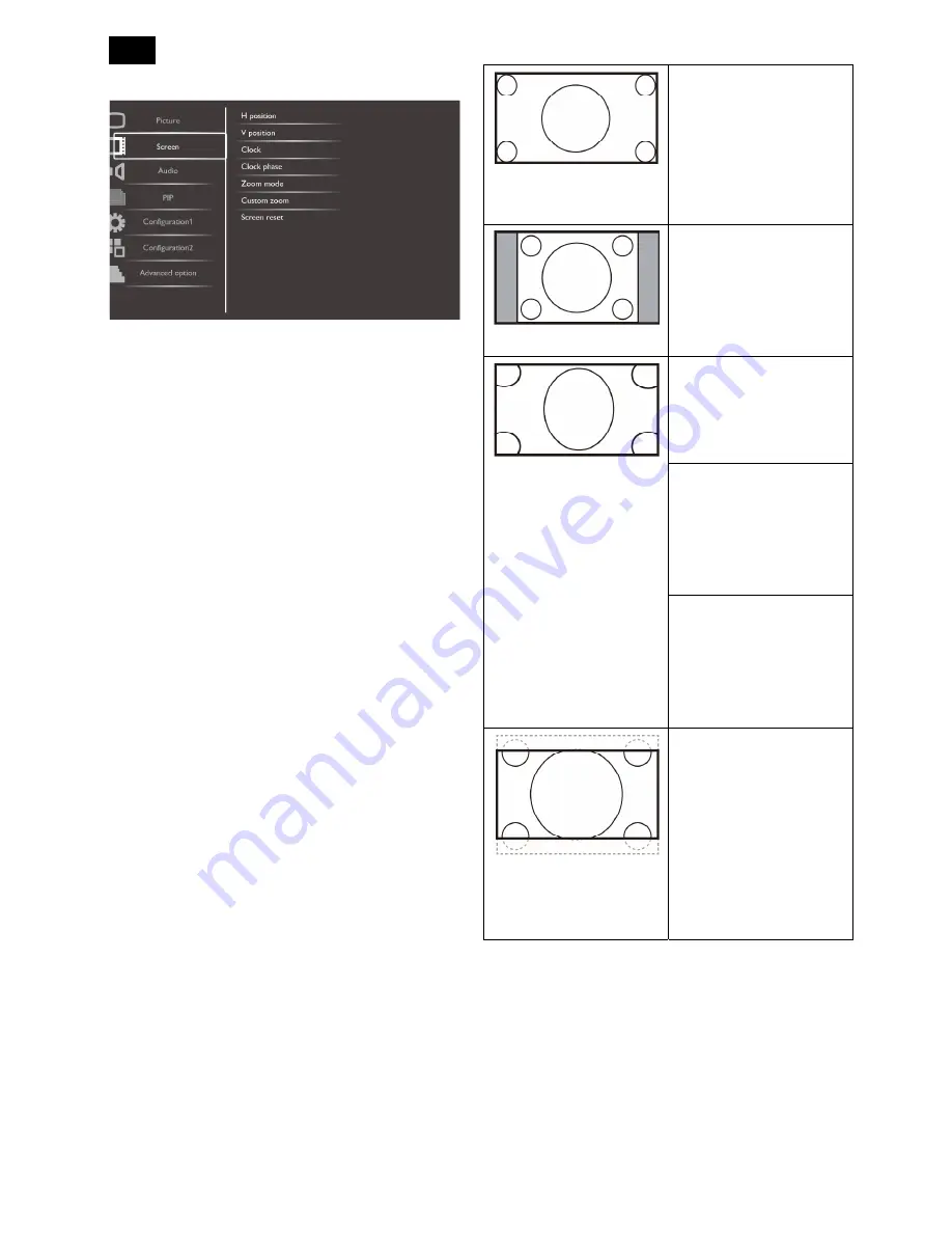
Zoom mode
The pictures you receive may be transmitted in 16:9
format (wide screen) or 4:3 format (conventional
screen). The 16:9 pictures sometimes have a black
band at the top and bottom of the screen (letterbox
format).
This function allows you to optimize the picture display
on screen. The following zoom modes are available
for:
PC mode: {Full} / {Normal} / {Custom} / {Real}.
Video mode: {Full} / {Normal} / {Dynamic} / {Custom}
/ {Real} / {21:9}.
Full
This mode restores the
correct proportions of
pictures transmitted in
16:9 using the full screen
display.
Normal
The picture is reproduced
in 4:3 format and a black
band is displayed on
either side of the picture.
Dynamic
Fill the entire screen by
stretching 4:3 pictures
non-proportionally.
Custom
Choose to apply the
custom zoom settings in
the Custom Zoom
submenu.
Real
This mode displays the
image pixel-by-pixel on
screen without scaling the
original image size.
21:9
The picture is enlarged to
16:9 format. This mode is
recommended when
displaying pictures that
have black bands at the
top and bottom (letterbox
format).
Custom zoom
You can use this function to further customize the
zoom settings to suit the image you want to display.
NOTE: This item is functional only when the Zoom
mode setting is set to Custom.
Summary of Contents for Signage Solutions E-Line Display BDL5551EL/00
Page 33: ...33 Meridian 1 5 Block Diagram 5 1 Scaler Board ...
Page 34: ...34 Power Board ...
Page 66: ...66 Remark Parts position can be searched by using FIND function in PDF ...
Page 75: ...75 3 Remove all the screws as follow ...
Page 76: ...76 76 4 Remove the main frame from the panel ...
Page 81: ...81 3 Set the parameters as below figure ...
Page 83: ...83 6 Click Commands batch to load the file isp_psi_ext txt ...
Page 87: ...87 ...
Page 89: ...89 ...
Page 92: ...92 92 5 Click Auto to upgrade 6 Update processing ...
Page 96: ...96 96 2 Tick the Analog DVI and click Loadfile to set the parameters 3 Select the EDID folder ...
Page 115: ...115 ...
Page 121: ...121 Service Kit Description Part No Picture ISP tool 715GT183 A DDC TOOL 715GT034 B ...


