Hardware Repair
MCP9360i
12.
EN 61
12.15.9. Motherboard Replacement
1.
Remove the motherboard subassembly. See paragraph 12.15.1.
2.
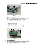
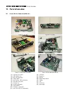
Remove the 2 thermistors (20). See Figure 12.15-12.
3.
Remove the SCART daughterboard. See paragraph 12.15.3.
4.
Remove the CPU. See paragraph 12.15.5.
5.
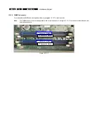
Remove all DIMMs. See paragraph 12.15.7.
6.
Remove the WLAN card. See paragraph 12.8.1.
7.
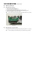
Remove the 2 mounting screws (21) from the motherboard tray back plate. See Figure 12.15-13.
8.
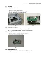
Remove the 7 mounting screws (22) from the motherboard tray base. See Figure 12.15-14.
9.
Remove the motherboard from the motherboard tray.
Figure 12.15-12
Figure 12.15-13
20
20
21
21
Figure 12.15-14
22
22
22
22
22
22
22
12.15.10. Motherboard Re-Assembly
To re-assemble the motherboard, do all steps described in paragraph 12.15.9 in reverse order.
Note:
The torque setting required for the motherboard tray backplate mounting screws (22) is 6 kg-cm.
The torque setting required for the motherboard tray base mounting screws (21) is 6 kg-cm.
Note:
After re-assembling the MCP9360i install the latest BIOS. See paragraph 9.2.

