English
17
Step 1: Basic Recorder Connections
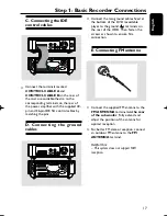
C. Connecting the IDE
control cables
COMPONENT VIDEO OUT
Connect the terminals marked
CONTROL CABLE A
and
CONTROL CABLE B
on the rear of
the micro recordable theatre to the
corresponding terminals on the rear of
the power amplifi er with the supplied 40-
pin and 36-pin IDE fl at control cables by
matching the pins.
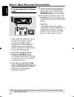
D. Connecting the ground
cables
COMPONENT VIDEO OUT
Connect the two ground cables fi xed at
the bottom of the DVD recordable
player to the ground ( ) terminals on
the rear of the HDD. Then, fasten the
screws as shown to ensure fi rm
connection.
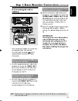
E. Connecting FM antenna
Connect the supplied FM antenna to the
FM ANTENNA
terminal
on the rear
of the subwoofer
. Fully extend and
adjust the position of the antenna for
optimal reception.
For better FM stereo reception, connect
an outdoor FM antenna to the
FM
ANTENNA
terminal.
Helpful Hint:
– This system does not support MW
reception.
pg001-pg080_RTH718_eng_98.indd 17
pg001-pg080_RTH718_eng_98.indd 17
2006-10-20 10:41:44 AM
2006-10-20 10:41:44 AM

