background image

38

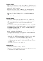
• Key test
   - Will allow you to test all the keys to make sure they are 
      functioning. Press all the keys one at a time.
• Display test
   - Tests all the display functions by lighting each LED light 
      sequentially.
• Functions (press confirm key to access menu)
   - Units
          Set to English (imperial units) or metric display readings. The
          default is imperial, which means data such as bodyweight and
          height will be in pounds and inches.
   - Pause mode
          Turn on allow 5 minutes of pause, turn off to have the console
          pause indefinitely.
   - Odometer reset
          Resets the odometer to zero (Time and distance)
   - Beep sound
          Turn on or off the speaker to silence beeping sound.
   - LED brightness
          Adjust the LED brightness.
   - Model
          Select the kind of device.
• Service
   - Brake test
          Adjust PWM value.
   - CSAFE test
          Test the CSAFE functions.
• ANT ID
   - Adjust the ANT ID.
• Update code
   - Switch bootloader on/off. The default is off.
• Exit
   - Press confirm key to leave maintenance mode and restart.

1

1

1

1

1

1

1

1

Summary of Contents for PTE4000CU

Page 1: ...ad this entire manual carefully before operating your new upright bike and save it for future use User manual Register your product and get support at www philips com welcome PTE4000CU ReActiv Upright bike 4 0 U ...

Page 2: ... dealers distributors and manufacturer s representatives we will do all we can to provide many years of successful and prosperous ownership Your warranty and service needs will be addressed either through your regional sales representative or our highly trained service technicians It is their responsibility to provide you with both the technical knowledge and access to service personnel to make yo...

Page 3: ...s Important safety instructions 4 Important electrical information Important operation instructions 7 Features 8 Assembly instructions 9 Console operation 14 6 Using a heart rate transmitter 34 Maintenance 37 ...

Page 4: ... they do not play with the device Keep hands away from all moving parts Never drop or insert any object into any openings Do not use outdoors Do not operate this product on deeply padded plush or shag carpet Damage to both carpet and product may result Do not attempt to use this product for any purpose other than for the purpose it is intended The hand pulse sensors are not medical devices Various...

Page 5: ...for use on your bike Quality athletic shoes are recommended to avoid leg fatigue This appliance is not intended for use by persons including children with reduced physical sensory or mental capabilities or lack of experience and knowledge unless they have been given supervision or instruction concerning use of the appliance by a person responsible for their safety Maximum User Weight 450 lbs Save ...

Page 6: ...ock could occur Never expose this product to rain or moisture This product is not designed for use outdoors near a pool or spa or in any other high humidity environment The operating temperature specification is 5 to 48 degrees Celsius 40 to 120 degrees Fahrenheit and humidity is 95 non condensing no water drops forming on surfaces Important electrical information ...

Page 7: ...onsole and release the adjustment key The console will obey the command gradually Use caution while participating in other activities while pedaling on your product such as watching television reading etc These distractions may cause you to lose balance which may result in serious injury Do not use excessive pressure on console control keys They are precision set to function properly with little f...

Page 8: ...ight bike Parts and adjustments 1 Console 2 Hand pulse grips 3 Fore aft seat adjustment 4 Vertical seat adjustment 5 Pedal 6 Leveling glides Optional parts not shown 2 1 Adjustable crank set Features 5 6 6 2 3 4 1 ...

Page 9: ...needed to avoid confusion The numbers in the instructions that are in parenthesis are the item number from the assembly drawing for reference Tools included 13 15mm wrench 12 14mm wrench 6 mm L allen wrench Phillips screwdriver Assembly instructions Parts included 1 main frame 1 rear stabilizer 1 console mast 1 handle bar 1 console mast cover 1 front stabilizer cover 1 rear stabilizer cover 1 cons...

Page 10: ...main frame 1 with the four hex head bolts 50 and four flat washers 71 Install the seat mount slide 7 onto the track on top of the seat tube with the seat post facing forward with the seat adjustment knob 86 flat washers 71 fixing plate 8 and nut 78 Part Type Description Hardware for step 1 Qty 50 71 78 Hex head bolt Flat washer Cap nut 3 8 2 1 4 Ø3 8 3 8 7T 4 5 1 50 50 71 71 5 1 100 86 7 8 78 71 1...

Page 11: ...console mast 2 to main frame 1 with 6 bolts 51 and 6 washers 72 on the both side screws 1 bolt 51 and 1 curved washer 99 on the front screw Do not pinch any wires Part Type Description Hardware for step 2 Qty 51 72 99 Hex head bolt Flat washer Curved washer 5 16 5 8 Ø5 16 Ø5 16 7 6 1 2 38 72 72 51 51 99 72 29 1 100 ...

Page 12: ...s 84 Run the 2 hand pulse wires 26 28 into the hole in the handle bar mounting plate and out through the hole in the console plate Part Type Description Hardware for step 3 Qty 57 60 64 84 Flat washer Socket head cap bolt Split washer Nyloc nut Ø8 5 M8 65L Ø8 1 5T M8 7T 8 4 4 4 117 81 84 57 57 64 60 28 26 3 2 ...

Page 13: ...s 75 Attach cup holder 116 to console mast 2 using 2 screws 75 Install the left and right pedals 45 46 onto the left and right crank arms 16 l 16 r The left pedal has a reverse thread and will be screwed in with the opposite rotation Make sure to tighten the pedals as much as possible Install the seat 19 onto the seat post 7 Part Type Description Hardware for step 4 Qty 74 75 Phillips head screw P...

Page 14: ...tart to pedal the console will turn on automatically The console will go to the start up display also known as Idle mode The message window will be scrolling the start up message You may now begin to use the 4 0 U Console operation Program keys 2 Dot matrix window 3 Function keys 4 Message window 1 Fan 5 Resistance level or adjustment up down keys 6 ...

Page 15: ...m zero all workout data will start to accrue and the workload may be adjusted manually by pressing the Plus and Minus keys As you increase the workload more rows will light indicating a harder workout The bike will get harder to pedal as the rows increase There are 40 levels of resistance available for plenty of variety The first 10 levels are very easy workloads and the changes between levels are...

Page 16: ...or pulse in beats per minute this may take a few seconds NOTE You must enter your correct age during program setup for heart rate control program to be accurate Refer to using a heart rate transmitter section for details about these features and how they can help you work out more efficiently The stop key actually has several functions Pressing the stop key once during a program will pause the pro...

Page 17: ... the correct number Your age is also necessary during the heart rate control program to ensure the correct settings are in the program for your age Otherwise the work settings could be too high or low for you entering your weight aides in calculating a more correct calorie reading Although we cannot provide an exact calorie count we do want to be as close as possible Calorie note Calorie readings ...

Page 18: ...may enter your age using the Plus and Minus keys then press the confirm button to accept the new number and proceed on to the next screen You are now asked to enter your weight You may adjust the weight number using the Plus and Minus keys then press confirm to continue The next setting is time You may adjust the Time and press confirm key to continue Now you are finished editing the settings and ...

Page 19: ...level you will experience during the program at the top of the hill Adjust the level and then press confirm Now you are finished editing the settings and can begin your workout by pressing the start button You can also go back and modify your settings by pressing the stop key to go back one level or screen If you want to increase or decrease the workload at any time during the program press the Pl...

Page 20: ...ovides a steady state exercise with warm up and cool down periods Interval The Interval program takes you through high levels of intensity followed by periods of low intensity This program increases your endurance by depleting your oxygen level followed by periods of recovery to replenish oxygen Your cardio vascular system gets programmed to use oxygen more efficiently this way ...

Page 21: ...ame saved you can change it or you may press the stop key to keep the name and continue to the next step If you want to enter a name use the plus and or the minus key to change the first letter then press confirm to save the first letter and continue to the next letter When you have finished entering the name press the stop key to save the name and continue to the next step The message window will...

Page 22: ...set The message window will then tell you to press confirm to save the program After saving the program the message window says new program saved then will give you the option to start or modify the program Pressing stop will exit to the start up screen During the custom program you will be able to scroll through the data in the message window by pressing the display key Use the heart rate monitor...

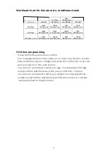
Page 23: ...mploys two to four stages lasting 3 minutes each of continuous exercise see charts below You will be prompted to choose either Male or Female at the beginning of the test This choice determines which protocol will be used during the test as shown in the charts below The only caveat is if you are a very de conditioned male you may need to choose option Female If you are a very conditioned female yo...

Page 24: ...ge using the Plus and Minus key then press confirm to continue You are now prompted to enter your weight You may adjust the weight using the Plus and Minus key then press enter to continue Now press start to begin the test 1st Stage 25W 150 kgm min Heart Rate HR 80 HR 80 90 HR 90 100 HR 100 2nd Stage 125W 750 kgm min 100W 600 kgm min 75W 450 kgm min 50W 300 kgm min 3rd Stage 150W 900 kgm min 125W ...

Page 25: ...RPM pedal speed If the pedal speed drops below 48 RPM or goes above 52 RPM the console will emit a steady beeping sound and the RPM number will flash until the speed is within this range You may scroll through the various data readings in the messag window by pressing the display key The message window will always display your pedal speed on the right side to help you maintain 50 RPM The data show...

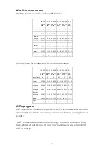
Page 26: ...s old years old years old excellent 60 56 51 45 41 37 good 43 51 52 60 49 56 39 45 36 41 33 37 above average 47 51 43 48 39 42 35 38 32 35 29 32 average 42 46 40 42 35 38 32 35 30 31 26 28 below average 37 41 35 39 31 34 29 31 26 29 22 25 poor 30 34 30 36 26 30 25 28 22 25 20 21 very poor 30 30 26 25 22 20 56 65 18 25 26 35 36 45 46 55 65 years old years old years old years old years old years old...

Page 27: ...ge Use the Plus and Minus keys to change and press the confirm key to continue You are now prompted to enter your weight You may adjust the age using the Plus and Minus key then press confirm key to continue You are now prompted to enter your workout time You may adjust the time using the Plus and Minus key then press confirm to continue You are now prompted to enter your target METs You may adjus...

Page 28: ...low walking 2 5 mph 4 km h bicycling stationary 50 watts very light effort walking 3 0 mph 4 8 km h calisthenics home exercise light or moderate effort general walking 3 4 mph 5 5 km h bicycling 10 mph 16 km h leisure to work or for pleasure bicycling stationary 100 watts light effort sexual activity jogging general calisthenics e g pushups situps pullups jumping jacks heavy Vigorous effort runnin...

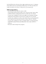
Page 29: ...n be accomplished by using the following formula 220 minus your age This will give you the maximum Heart rate MHR for someone of your age To determine the effective heart rate range for specific goals you simply calculate a percentage of your MHR Your Heart rate training zone is 50 to 90 of your maximum heart rate 60 of your MHR is the recommended for burning fat while 80 is recommended for streng...

Page 30: ...cardiovascular fitness or if it is weight loss it can be achieved by training at 80 or 60 respectively of your MHR on a schedule approved by your physician Consult your physician before participating in any exercise program With all heart rate programs you may use the heart rate monitor feature without using the Heart Rate program This function can be used during manual mode or during any other di...

Page 31: ...cussed earlier That is the major benefit of this type of training If your body is strong and rested you will feel strong and your pace will feel easier When your body is in this condition you are able to train harder and the RPE will support this If you are feeling tired and sluggish it is because your body needs a break In this condition your pace will feel harder Again this will show up in your ...

Page 32: ...ou are asked to adjust the target HR This is the 65 80 heart rate level you will experience during the program Adjust the target number and then press confirm Now you are finished editing the settings and can begin your workout by pressing the start key You can also go back and modify your settings by pressing the confirm key NOTE At any time during the editing of data you can press the Stop key t...

Page 33: ... the console will automatically switch to HR control and will maintain your current HR To start the HR auto pilot mode follow the instructions below and the directions in the message window Press the HR auto pilot key during the fitness programs and it is necessary to wear HR strap to enter this mode If a HR is not detected the message window shows NO HEART RATE At the end of the HR auto pilot pro...

Page 34: ...tightly as possible as long as the strap is not too tight to remain comfortable Position the transmitter with the logo centered in the middle of your body facing away from your chest some people must position the transmitter slightly left of center Attach the final end of the elastic strap by inserting the round end and using the locking parts secure the transmitter and strap around your chest Pos...

Page 35: ...nge distance between transmitter receiver to achieve a strong steady signal The length of range may vary somewhat but generally stay close enough to the console to maintain good strong reliable readings Wearing the transmitter immediately against bare skin assures you of proper operation If you wish you may wear the transmitter over a shirt To do so moisten the areas of the shirt that the electrod...

Page 36: ...y systems Perimeter fence for a pet Some people have problems with the transmitter picking up a signal from their skin If you have problems try wearing the transmitter upside down Normally the transmitter will be oriented so the logo is right side up The antenna that picks up your heart rate is very sensitive If there is an outside noise source turning the whole machine 90 degrees may de tune the ...

Page 37: ...ssues can be traced to loose hardware The crank arm nut and or the pedals need to be retightened If squeaks or other noises persist check that the unit is properly leveled There are 2 leveling pads on the bottom of the rear stabilizer use a 14mm wrench or adjustable wrench to adjust the levelers Maintenance mode in console software The console has built in maintenance diagnostic software The softw...

Page 38: ...ight and height will be in pounds and inches Pause mode Turn on allow 5 minutes of pause turn off to have the console pause indefinitely Odometer reset Resets the odometer to zero Time and distance Beep sound Turn on or off the speaker to silence beeping sound LED brightness Adjust the LED brightness Model Select the kind of device Service Brake test Adjust PWM value CSAFE test Test the CSAFE func...

Page 39: ... 80 47 54 15 22 79 54 16R 96 83 11 107 39 6 114 70 82 59 35 82 70 35 59 13 45 46 118 80 31 102 23 35 35 61 86 71 19 8 7 78 54 76 69 20 76 69 68 68 106 2 106 97 97 17 150 2019 05 07 2 03 A 03 B 03 C 21 26 28 32 32 34 01 34 02 34 03 34 04 34 08 34 12 34 13 34 14 34 15 34 07 34 06 34 05 34 09 34 10 34 11 42 43 58 58 62 65 62 65 51 51 51 99 72 72 57 57 57 57 60 64 64 84 74 75 75 81 116 53 75 75 75 75 ...

Page 40: ... Fix plate Idler wheel assembly Crank axle Chain cover bracket Drive belt Drive pulley Crank arm l Crank arm r 6004_bearing 6203_bearing Seat Induction brake Generator brake controller Magnet Sensor w cable 950m m_handpulse wire XHP 3 950m m_handpulse wire XHP 4 2100m m_computer cable 200m m_wire brake coil harness Generator wire harness 30m m_handpulse assembly Console assembly Console top cover ...

Page 41: ...ard Faceplate label Fan grill anchor Wind duct End cap Rubber foot Chain cover l Chain cover r Console mast cover Seat post cover Front stabilizer cover Rear stabilizer cover Console chin cover End cap Pedal l Pedal r Transportation wheel 3 8 2 1 4 _hex head bolt 5 16 5 8 _hex head bolt 5 19m m_tapping screw 5 16 1 3 4 _button head socket bolt 1 4 3 4 _hex head bolt M8 170m m_j bolt M6 15m m_phill...

Page 42: ...ing 4 12m m_sheet metal screw 1 4 13 1t_flat washer Ø3 8 ø19 1 5t_flat washer Ø3 8 ø25 2 0t_flat washer Ø5 16 ø18 1 5t_flat washer Ø17 23 5 1t_flat washer M5 6l_phillips head screw M5 12l_phillips head screw Ø1 4 _split washer M8 7t_nyloc nut 3 8 7t_cap nut 1 4 8t_nyloc nut 5 16 6t_nyloc nut 6_l allen wrench 3 8 7t_nut M10 p1 25 10t_ nut M8 7t_nyloc nut Round disk Fore aft adjustment knob Phillips...

Page 43: ...06 106 2 107 114 116 117 118 150 12 14m m_wrench Ø5 16 16 1 0t_flat washer Knob adjustor M4 5l_phillips head screw Slider sleeve Slide spacer Drink bottle holder 13 15m m_wrench 5 16 2 1 4 _hex head bolt Rubber pad 1 2 1 2 1 1 1 1 2 1 ...

Page 44: ... discretion to remedy faults giving rise to applicable warranty claims The warranty periods set out below are subject to the performance of proper care and maintenance as set out in this user manual by the original purchaser of the equipment Warranties are not transferable Wear items are rubber hand grips pedals console overlay and drive belt Normal responsibilities of the facility The facility is...

Page 45: ...idental or consequential damages so this limitation or exclusion may not apply to you Service call reimbursement to the dealer that does not involve malfunction or defects in workmanship or material for units that are beyond the warranty period for units that are beyond the service call reimbursement period or units not requiring component replacement Damages caused by services performed by person...

Page 46: ...sfunction increase joint mobility muscle performance and neuromuscular performance Physical therapists select prescribe and implement the use of biophysical agents when the examination findings diagnosis and prognosis indicate the use of these agents to reduce risk factors and complications enhance health wellness or fitness enhance or maintain physical performance or prevent or remediate impair m...

Page 47: ...gh one of our authorized service centers All repairs must be preauthorized by Dyaco If the product is shipped to a service center freight charges to and from the service center will be the customer s responsibility The owner is responsible for adequate packaging upon return to Dyaco Dyaco is not responsible for damages in shipping Make all freight damage claims with the appropriate freight carrier...

Page 48: ...d Emblem are registered trademarks of Koninklijke Philips N V and are used under license This product has been manufactured by and is sold under the responsibility of Dyaco Commercial Medical North America LLC and Dyaco Commercial Mediacl North America LLC is the warrantor in relation to this product ...

Reviews: