2-1
2-1
DISMANTLING INSTRUCTIONS
Dismantling of the PCB assemblies and modules
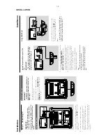
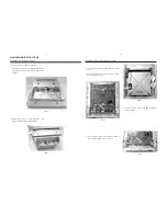
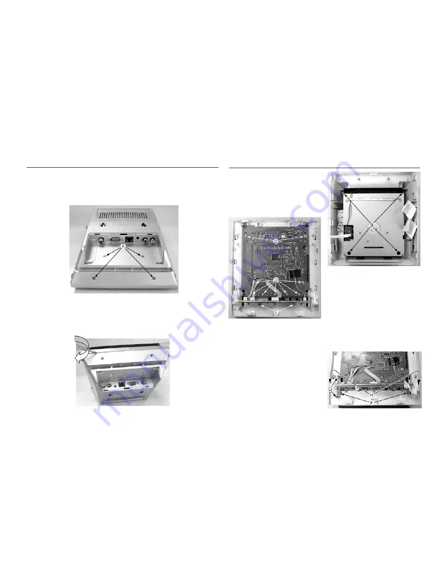
1) Loosen 4 screws B to remove DVD Loader as shown in
Figure 3.
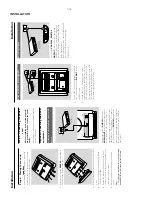
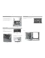
2) Loosen 2 screws C and 7 screws D to remove the Display
Board as shown in Figure 4.
Dismantling of the Front Panel assembly
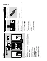
1) Loosen & remove 4 screws A (see figure 1).
2) Place a small flat screw driver in between the front & rear
cabinets and roll the screw driver along the joint as shown
in figure 2.
Figure 2
Figure 1
Figure 3
3) Release total 6 catches on left and right side of rear
cabinet to separate it from the rear assembly.
3) Loosen 2 screws E to remove the AMP Key Board as
shown in Figure 4.
Figure 4
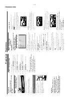
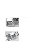
4) Loosen 2 screws F and 4 screws G and 2 screws H to
remove Swing System as shown in Figure 5.
Figure 5
Summary of Contents for MCD288
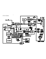
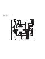
Page 18: ...4 1 SET BLOCK DIAGRAM 4 1 ...
Page 19: ...5 1 SET BLOCK DIAGRAM 5 1 ...
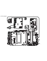
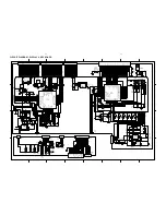
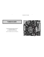
Page 21: ...6 2 6 2 LAYOUT DIAGRAM DISPLAY BOARD TOP VIEW ...
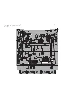
Page 22: ...LAYOUT DIAGRAM DISPLAY BOARD BOTTOM VIEW 6 3 6 3 ...
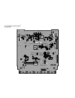
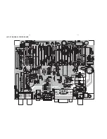
Page 27: ...8 2 8 2 LAYOUT DIAGRAM POWER BOARD ...

