1-8
INSTALLATION
Installation
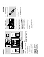
IMPOR
T
ANT!
–
The type plate is located at the r
ear of
the system.
–
Bef
or
e connecting the
AC
po
wer cor
d
to the wall outlet,
ensur
e that all other
connections ha
v
e been made
.
–N
ev
er mak
e or chang
e an
y
connections with the po
wer s
witched on.
–
High v
oltag
e! Do not open.
Y
ou run the
risk of g
etting an electric shock.
–
The machine does not contain any
user
-ser
viceab
le par
ts.
–
Modification of the pr
oduct could
result in hazar
dous radiation of EMC or
other unsaf
e operation.
To
av
oid o
verheating of the system,
a safety
circuit has been built in.
Ther
efore
, your
system may s
witch to Standb
y mode
automatically under e
xtr
eme conditions
. If
this happens
, let the system cool do
wn
befor
e r
eusing it
(not availab
le f
or all ver
sions).
Note:
–
Bef
or
e installation is f
inished,
it is not
recommended to remo
ve the pr
otective plastic f
ilm
attached to the surf
ace of the front panel to avoid
any scr
atc
h caused dur
ing installation.
AUDIO
IN
S-VIDEO
IN
VIDEO IN
TV IN
AUDIO
IN
S-VIDEO
IN
VIDEO IN
TV IN
AC
p
o
w
er cor
d
Speak
er
(right)
Speak
er
(left)
FM wir
e antenna
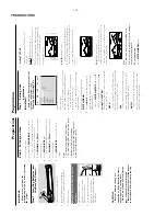
Step 2:
FM antenna connection
Connect the supplied FM antenna to the
FM
AERIAL
ter
minal.
Full
y extend and adjust the
position of the antenna f
or optimal reception.
For better FM stereo reception, connect an
outdoor FM antenna to the FM
AERIAL (FM
ANTENNA) ter
minal.
Notes:
–
This system does not suppor
t MW r
eception.
Installation
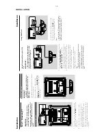
Step 1:
Connecting speak
ers
1
Place the main set with the front side facing
down on a flat and f
ir
m surface
. Then remo
ve
the detachab
le co
ver on the back of the set to
expose the ter
minals a
vailab
le f
or connection.
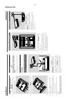
2
Connect the tw
o front speak
er cab
les to the
SPEAKER OUT
ter
minals:
r
ight speak
er to "R"
and left speak
er to "L".
3
Connect one end of the 15-pin D-Sub cab
le
(the other end is f
ix
ed on the
CONNECT T
O
SUBW
OOFER
ter
minal on the back of the
main set) to the
CONNECT T
O
MAIN
ter
minal of the subw
oofer b
y matching the pins.
Fix the tw
o screws on the connector
s to ensure
firm
connection.
Notes:
–
Ensur
e that the speak
er cables ar
e corr
ectly
connected.
Impr
oper connections may damage the
system due to shor
t-circuit.
–F
or optimal sound perf
ormance
, use the
supplied speak
er
s.
–
Do not connect mor
e than one speak
er to any
one pair of +/- speak
er terminals
.
–
Do not connect speak
er
s with an impedance
lo
wer than the speak
ers supplied.
Please r
ef
er to
the SPECIFIC
ATIONS section of this manual.
Summary of Contents for MCD288
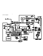
Page 18: ...4 1 SET BLOCK DIAGRAM 4 1 ...
Page 19: ...5 1 SET BLOCK DIAGRAM 5 1 ...
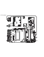
Page 21: ...6 2 6 2 LAYOUT DIAGRAM DISPLAY BOARD TOP VIEW ...
Page 22: ...LAYOUT DIAGRAM DISPLAY BOARD BOTTOM VIEW 6 3 6 3 ...
Page 27: ...8 2 8 2 LAYOUT DIAGRAM POWER BOARD ...

