7-3
Direction of Use
3 Before
use
Place the unit
Note
•
Risk of overheating! Never install this
apparatus in a confined space.Always leavea
space of at least 4 inches around this apparatus
for ventilation. Ensure curtains or other
objects never cover the ventilation slots on
this apparatus.
•
Place this unit on a flat,hard,and stable
surface.
•
Never place this unit in an enclosed cabinet,
nor on any other electrical equipment.
•
Do not insert any object other than indicated
into ventilation openings nor other openings.
•
Install this unit near the AC outlet where the
AC power plug can be easily reached.
•
To avoid magnetic interference or unwanted
noise, never place the main unit and speakers
too close to any radiation devices.
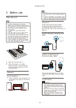
1
Place the unit near to the TV.
2
Place the speakers at a suitable
distance from the TV and at an angle
of approximately 45 degrees from the
listening position.
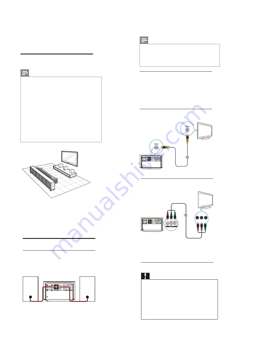
Connect
Connect speakers
1
Insert the speaker wires completely into
the speaker input sockets on the back of
the unit.
Option 2: Connect through
component video cables
Connect a progressive scan TV through
component video cables for higher quality
video.
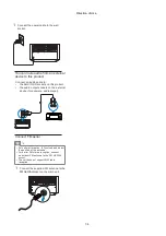
Connect power
Caution
•
Risk of product damage! Ensure that the
power supply voltage corresponds to the
voltage printed on the back or the underside
of the unit.
•
Risk of electric shock! When you unplug the
AC power cord, always pull the plug from the
socket. Never pull the cord.
•
Before you connect the AC power cord,
ensure that you have completed all other
connections.
Pr/Cr
Y
Pb/Cb
Note
•
For optimal sound, use the supplied speakers
only.
•
Connect only speakers with impedance that is
the same or higher than the supplied speakers.
Refer to the Specifications section of this manual.
Connect TV
Connect the audio and video cables to
the output sockets on the unit and the
corresponding input sockets on your TV.
Select the best video connection that your TV
supports.
Connect through a composite video
cable
Summary of Contents for MCD2010/12/93
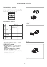
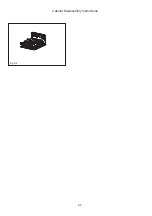
Page 26: ...8 2 Fig D4 Cabinet Disassembly Instructions ...
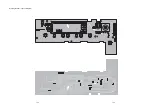
Page 33: ...Display Board Layout Diagram 12 3 12 3 ...
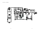
Page 35: ...Power Board Layout Diagram 12 5 12 5 ...
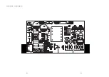
Page 42: ...Decoder Board Layout Diagram 12 12 12 12 ...
Page 44: ...Revision List Revision List Version 1 0 Initial Release 14 1 ...

