


Schematics and PWB’s
7.
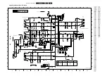
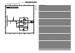
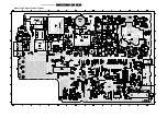
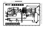
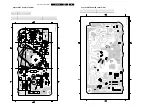
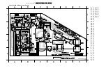
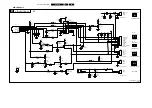
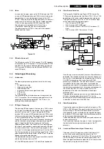
EPS 4B (External Power Supply)
2
3
4
5
6
7
B
C
D
E
F
G
B
C
D
E
F
G
2
3
4
5
6
7
1
1
A
A
H
8
8
H
To
0228
(Interface)
J
To
Ground
Pin
0285
of
Main
Chassis
RH3.5*0.8*4.7
13K
EE16
TOP233Y
1A 600V
5W 180V
0.001UF/1KV
43R
560R
0.001UF/1KV
0.001UF/1KV
43R
0.001UF/1KV
680UF/10V
330UF/25V
5A 40V
5A 40V
43R
3A 100V
3A 100V
KA278R12
KA278R05
470UF/10V
22R
47UF/16V
0.1UF/ 50V
0.1UF/50V
250mA
200V
470PF/
250V
TLP721
10A 30V
22R
0.01UF/1KV
UU9.8 22MH
UU9.8 22MH
1A/250V
0.1UF/275VAC
1A 600V
1.5M(1/2W)
7.5M
33UF/450V
5W 400V
2K
3.3K
10K
0.22UF/50V
AN1431
100R(1/4W)
510R
0.1UF/50V
470UF/10V
470UF/25V
470UF/10V
DR6*8 16UH
1A 100V
1A 100V
RH-3.5*0.8*9
220UF/10V
RH-3.5*0.8*9
RH-3.5*0.8*9
!
To
0211
(Power Supply)
A1
!
!
COLD Ground
HOT Ground
F
EPS 4B (External Power Supply)
CL16532138_001.eps
010302
Summary of Contents for L01H.1A
Page 5: ...Directions for Use EN 5 L01H 1A 3 3 Directions for Use ...
Page 7: ...Directions for Use EN 7 L01H 1A 3 ...
Page 8: ...Directions for Use EN 8 L01H 1A 3 ...
Page 9: ...Directions for Use EN 9 L01H 1A 3 ...
Page 10: ...Directions for Use EN 10 L01H 1A 3 ...
Page 11: ...Directions for Use EN 11 L01H 1A 3 ...
Page 12: ...Directions for Use EN 12 L01H 1A 3 Personal Notes ...


