Alignments
8.
8.
Alignments
Index:
General Alignment Conditions
Hardware Alignments
Software Alignments and Settings
Note:
•
The Service Default Alignment Mode (SDAM) is described
in chapter 5.
•
Menu navigation is done with the 'CURSOR UP, DOWN,
LEFT or RIGHT' keys of the remote control transmitter.
•
Figures can deviate slightly from the actual situation, due
to different set executions or software versions.
8.1
General Alignment Conditions
Perform all electrical adjustments under the following
conditions:
•
AC voltage and frequency: according to country's
standard.
•
Connect the set to the AC power via an isolation
transformer.
•
Allow the set to warm up for approximately 20 minutes.
•
Measure the voltages and waveforms in relation to chassis
ground (with the exception of the voltages on the primary
side of the power supply). Never use the cooling fins /
plates as ground.
•
Test probe: Ri > 10 M
Ω
; Ci < 2.5 pF.
•
Use an isolated trimmer / screwdriver to perform the
alignments.
8.2
Hardware Alignments
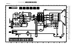
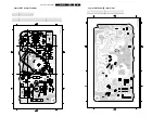
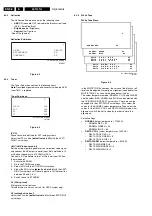
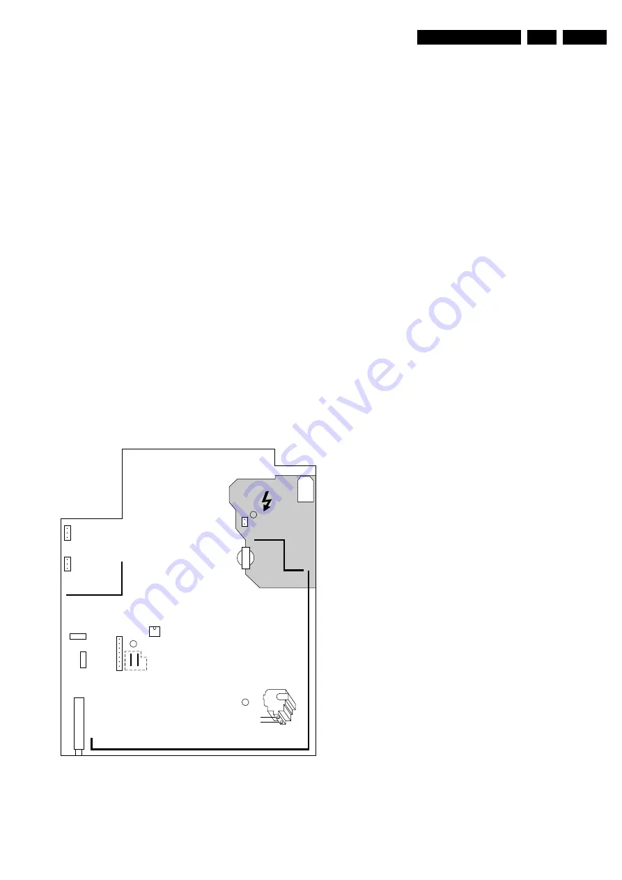
Figure 8-1 Hardware Alignments
8.2.1
Vg2 Adjustment (AKB method)
1.
Connect the RF output of a pattern generator to the
antenna input. Test pattern is a 'black' picture (blank
screen on CRT without any OSD info). 0r set TV to AV
mode.
2.
Activate the SDAM.
3.
Select options and set item "protection" to off.
4.
Select Deflection menu:
–
Set AKB to 1 (is OFF position, CCC loop disabled)
–
Set BRIGHTNESS to 75%
–
CONTRAST to zero.
5.
Unplug deflection coil connector "0222" (one bright vertical
line).
6.
Adjust VG2 until vertical line just appears.
7.
Connect back the deflection coil connector "0222"
8.
Set AKB back to 0 (=ON).
9.
Restore BRIGHTNESS and CONTRAST to normal picture
setting.
10. Select options and set item "protection" back to on.
11. Return to the SDAM (main menu) via the MENU key
12. Exit service mode
8.2.2
Focusing
1.
Tune the set to a circle or crosshatch test pattern (use an
external video pattern generator).
2.
Choose picture mode NATURAL with the 'SMART
PICTURE' button on the remote control transmitter.
3.
Adjust the FOCUS potentiometer (see Fig. 8-1) until the
vertical lines at 2/3 from east and west, at the height of the
centreline, are of minimum width without visible haze.
8.3
Software Alignments and Settings
Enter the Service Default Alignment Mode (see chapter 5).
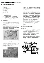
The SDAM menu will now appear on the screen.
Select one of the following alignments:
1.
OPTIONS
2.
DEFLECTION
3.
TUNER
4.
WHITE TONE
5.
GEOMETRY
0231
0212
C
16532108_013.eps
010302
A
B
5445
LOT
Focus
Screen
VG2
5520
0240
0267
0268
7602
1004
1002
1000 (TUNER)
9631
9641
SDAM
0231
Summary of Contents for L01H.1A
Page 5: ...Directions for Use EN 5 L01H 1A 3 3 Directions for Use ...
Page 7: ...Directions for Use EN 7 L01H 1A 3 ...
Page 8: ...Directions for Use EN 8 L01H 1A 3 ...
Page 9: ...Directions for Use EN 9 L01H 1A 3 ...
Page 10: ...Directions for Use EN 10 L01H 1A 3 ...
Page 11: ...Directions for Use EN 11 L01H 1A 3 ...
Page 12: ...Directions for Use EN 12 L01H 1A 3 Personal Notes ...


