F
A
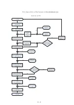
AII Function NO Working
Check AII System, AII Coble
is Loose or bad: INT
RE-insert and fix the
cable
Panel stand LED show
working or Not
Check Back Power PCB
F901 Bad cause Damage
Change F901
Check Con902 pin1
+5V affirm Correct
Repair between T901
Circuit
Check control PCB
IC901 and their conjoint
Part
Check CON903 PIN2
M5V affirm Correct
Check Switch power
Supply Circuit
Check Repair
U102,U104,U105,U106
Circuit
E
F
B
Power supply NO
Working
+27V Voltage No
Output
Check F901 Bad
Cause Damage
Check ic901
Working Or Not
Check power
Transformer Working
Or Not
ALL voltage No
output
+5V Voltage No
Output
+/-12v Voltage No
Output
Check cn801 vcc
Voltage=27V
Check D911 D912
and its conjoint part
Check D908 D910
and its conjoint part
Check Q901 and its
conn circuit
Repair The Part
Repair The part
Check Repair D905 and
conn circuit
C
Check D916 and its
conjoint part
ALL Function No
Sound
Check ic801a ic801b pin
23 Voltage is 3.3v
Check IC801A IC801B
Voltage correct is ok
See Contents B
Check repair D916 and its
conjoint part
Check repair Q804=3.3V
and its conjoint part
DVD Audio not
sound
Check open/close and disc
change working or not
Re-insert and fix the
cable
Hae picture output Yes
or No
Check IC u102 AND
con100 its conjoint part
Check cn102 cn101and
cn105 to dvd loader,
cable loose or bad int
Check U102 and their
cojoint part
Check cn102 to DVD
loader loose or bad not
Check ic804 their
conjoint part
Check repair Between
ic801
E
Aux/TV in No
Sound
Tuner NO Sound
Check U109 and its conjoint
part offirm working
Check repair Between
L131=5V and their conjoint
part
Check U107 U108 and its
conjoint part offirm working
Check U107 U108 PIN7=-5.1
pin16=+5V
Check between U102
PIN162 163 164 and their
cojoint part
Check cn111
pin9=9V
According AUX/TV
REPAIR
Check IC112 PIN4=-12V
PIN8=+12V and other
conjoint part
Check u102 PIN198 199 200
and pin201 other conjoint part
Alternate tuner
Check D101
Voltage=10.1v
Check Q101 and
their conjoint part
Check servo pcb
Check U100 PIN2 1V8
Check U101 PIN2 3V3
D
Check U102 PIN109,210,211and
214 its conjoint part
AII Function NO
Working
Power supply NO
working
ALL Function NO
Sound
Aux/TV in NO
Sound
Tuner NO Sound
YES
not bad
no
ok
not
ok
not
not
ok
not
YES
ALL voltage No
output
YES
working
not
not
not
not
not
not
not
yes
yes
not
not
not
not
ok
ok
ok
YES
YES
not
not
ok
not
ok
not
not
not
D
DVD Audio NO
Sound
A
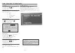
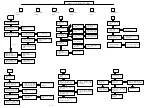
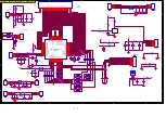
MAIN UNIT REPAIR CHART
B
C
3 - 5
Summary of Contents for HTS3021/94
Page 14: ...3 4 ...
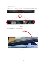
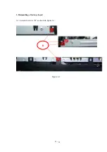
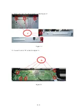
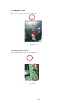
Page 18: ...3 Dismantling of 3 1 Loosen 4 screws B as shown in figure 3 1 Figure 3 1 B 4 3 led key board ...
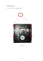
Page 20: ...4 Dismantling of loader 4 1 Loosen 4 screws E as shown in figure 4 1 E Figure 4 1 4 5 ...
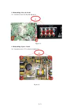
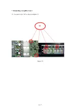
Page 22: ...7 Dismantling of amplifier board 7 1 Loosen 4 screw H as shown in figure 7 1 Figure 7 1 H 4 7 ...
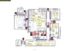
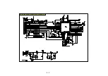
Page 24: ...5 1 C4 C2 C1 C3 C5 C6 C7 C8 C10 C11 C13 C12 BLOCK WIRING DIAGRAM C9 ...
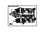
Page 25: ...6 1 AMPLIFIER BOARD SCHEMATIC DIAGRAM 1 3 ...
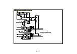
Page 26: ...6 2 AMPLIFIER BOARD SCHEMATIC DIAGRAM 2 3 ...
Page 27: ...6 3 AMPLIFIER BOARD SCHEMATIC DIAGRAM 3 3 ...
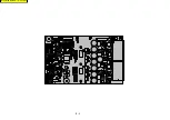
Page 28: ...6 4 AMPLIFIER BOARD TOP VIEW ...
Page 29: ...6 5 AMPLIFIER BOARD BOTTOM VIEW ...
Page 31: ...7 2 LED BOARD TOP VIEW KEY BOARD TOP VIEW LED KEY BOARD TOP VIEW ...
Page 32: ...LED BOARD BOTTOM VIEW KEY BOARD BOTTOM VIEW 7 3 LED KEY BOARD BOTTOM VIEW ...
Page 39: ...8 7 DECODE BOARD TOP VIEW ...
Page 40: ...8 8 DECODE BOARD BOTTOM VIEW ...
Page 42: ...9 2 POWER BOARD TOP VIEW ...
Page 43: ...9 3 POWER BOARD BOTTOM VIEW ...
Page 44: ...10 1 MECHANICAL EXPLODE VIEW ...
Page 51: ...REVISION LIST Version 1 0 Initial release 11 1 ...


