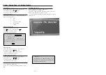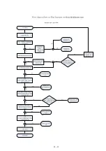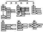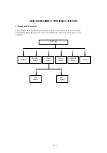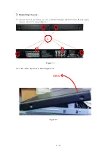
System , Region Code , etc. Setting Produre
1)System Reset
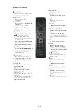
a) Press “SETUP“ button on RC,TV will show setup menu
b) Select the menu using the and on RC
c) Go preference page to do system reset
2)Region Code Change
a) In open model, press”9” “9“ “9“ “9“ on R/C,then input desired
number to change region code :
1 USA
2 EU
3 AP
4 Australia ,NZ , Latam
5 Russia , INDIA
6 CHINA
3)Version Control Change
a) In open model, press “1“ “5“ “9“ on RC
c) Press and “ok” button to confi rm
d) TV will show message as below:
7) Upgrading new sofeware
a) Copy “sofeware fi les” into a CD-R or USB flash drive.
b) Insert the CD-R disc or USB flash drive.
c) Press DISC or USB, the system will identify the update file autometically.
d) VFD will show “Updating“ until update is complete.
* the system will switch off to standby automatically after update is complete.
e) OSD will show:
Current model
HTS3021/98
Ver18.04.2M _090211_0 Region
: 3
Servo: AE.56.00.00
8032: 05.00.04.06 RISC: 05.02.00.24
IF current model does not match you set use down arrow
key on the remote to change
OK
CAUTION!
This information is confi dential and may not be
distributed.Only a qualifi ed service person should
reprogram the Region Code.
4)Password Change
a) Press “SETUP“ button on R/C,TV will show setup menu
b) Select the menu using the and on RC
c) Go preference page select “password“ to change
* 136900 is default password supplied.
5)Check on the Sofeware Version
TV will show the version on screen.
6)Trade model
a) Press “Open/Close “ button on RC
b) Press “2” “5” “9” on R/C,VFD will display “TRA ON “ or “TRA
OFF“
b) Press and select version you want using
a) Press “SETUP“ button on R/C,TV will show setup menu
b) Select the menu using the and on RC
c) Go preference page select “Version Info“.
3 - 3
/9 4
Summary of Contents for HTS3021/94
Page 14: ...3 4 ...
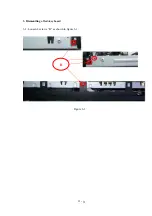
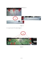
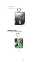
Page 18: ...3 Dismantling of 3 1 Loosen 4 screws B as shown in figure 3 1 Figure 3 1 B 4 3 led key board ...
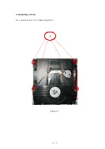
Page 20: ...4 Dismantling of loader 4 1 Loosen 4 screws E as shown in figure 4 1 E Figure 4 1 4 5 ...
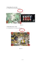
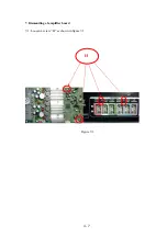
Page 22: ...7 Dismantling of amplifier board 7 1 Loosen 4 screw H as shown in figure 7 1 Figure 7 1 H 4 7 ...
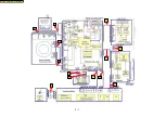
Page 24: ...5 1 C4 C2 C1 C3 C5 C6 C7 C8 C10 C11 C13 C12 BLOCK WIRING DIAGRAM C9 ...
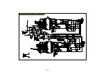
Page 25: ...6 1 AMPLIFIER BOARD SCHEMATIC DIAGRAM 1 3 ...
Page 26: ...6 2 AMPLIFIER BOARD SCHEMATIC DIAGRAM 2 3 ...
Page 27: ...6 3 AMPLIFIER BOARD SCHEMATIC DIAGRAM 3 3 ...
Page 28: ...6 4 AMPLIFIER BOARD TOP VIEW ...
Page 29: ...6 5 AMPLIFIER BOARD BOTTOM VIEW ...
Page 31: ...7 2 LED BOARD TOP VIEW KEY BOARD TOP VIEW LED KEY BOARD TOP VIEW ...
Page 32: ...LED BOARD BOTTOM VIEW KEY BOARD BOTTOM VIEW 7 3 LED KEY BOARD BOTTOM VIEW ...
Page 39: ...8 7 DECODE BOARD TOP VIEW ...
Page 40: ...8 8 DECODE BOARD BOTTOM VIEW ...
Page 42: ...9 2 POWER BOARD TOP VIEW ...
Page 43: ...9 3 POWER BOARD BOTTOM VIEW ...
Page 44: ...10 1 MECHANICAL EXPLODE VIEW ...
Page 51: ...REVISION LIST Version 1 0 Initial release 11 1 ...


