2-2
SPR 00 0106
8
E n g l i s h
General Inf
ormation
This system complies with the FCC rules
,
Pa
rt
15 and with 21 CFR 1040.10.
Oper
ation is subject to the follo
wing two
conditions:
–
This de
vice may not cause harmful
interference
, and
–
This de
vice m
ust accept an
y interfer
ence
receiv
ed,
including interfer
ence that may
cause undesir
ed oper
ation.
En
vir
onmental Inf
ormation
All unnecessar
y packaging has been omitted.
W
e
ha
ve
tr
ied to make the packaging easy to
separ
ate into three mater
ials:
cardboard (bo
x),
polystyrene f
oam (b
uff
er) and poly
eth
ylene (bags,
protective f
oam sheet).
Your system consists of mater
ials which can be
recycled and reused if disassemb
led b
y a
specializ
ed compan
y. Please obser
ve
the local
regulations regarding the disposal of packaging
mater
ials,
exhausted batter
ies and old
equipment.
Ackno
wledg
ement
Energ
y Star
As an ENERGY ST
AR
R
Pa
rtner
; Philips has
deter
mined that this product
meets the ENERGY ST
AR
R
guidelines f
or ener
gy eff
iciency
.
Dolb
y
Manufactured
under license
from Dolb
y Labor
ator
ies.
“PR
O-LOGIC” and the
doub
le-D symbol
d
are tr
ademar
ks of Dolb
y
Labor
ator
ies.
Conf
idential unpub
lished w
o
rks.
C
1992-1997 Dolb
y Labor
ator
ies.
All r
ights
reser
ved.
Supplied accessories
–
Remote control
–
Batter
ies (tw
o
AA siz
e) f
or remote control
–
AM loop antenna
–
FM wire antenna
–A
C po
w
er cord
–
CS-900 speaker package (includes one pair of
sur
round speak
er
s and one center speak
er)
–S
W
-900 po
w
ered subwoof
er
Saf
ety Inf
ormation
●
Before oper
ating the system,
check that the
oper
ating v
oltage indicated on the typeplate (or
the v
oltage indication beside the v
oltage
selector) of y
our system is identical with the
voltage of y
our local po
w
er suppl
y. If not,
please
consult y
our dealer
.
●
Place the system on a flat,
hard and stab
le
surface
.
●
Place the system in a location with adequate
ventilation to prev
ent inter
nal heat b
uild-up in
your system.
Allo
w at least 10 cm (4 inches)
clear
ance from the rear and the top of the unit
and 5 cm (2 inches) from each side
.
●
Do not expose the system,
batter
ies or discs to
excessiv
e moisture
, r
ain,
sand or heat sources
caused b
y heating equipment or direct sunlight.
●
If the system is brought directly from a cold to a
war
m location,
or is placed in a v
e
ry
damp room,
moisture ma
y condense on the lens of the disc
unit inside the system.
Should this occur
, the CD
pla
yer will not oper
ate nor
mall
y. Lea
ve
the
po
wer on f
or about one hour with no disc in the
system until nor
mal pla
yback is possib
le
.
●
The mechanical par
ts of the set contain self-
lubr
icating bear
ings and m
ust not be oiled or
lubr
icated.
●
When the system is switched to Standb
y
mode
, it is still consuming some po
w
e
r.
To
disconnect the system fr
om the
po
w
er supply completel
y,
r
emo
v
e
the
A
C
po
w
er plug fr
om the wall sock
et.
9
En
gli
sh
Pr
eparations
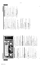
Rear Connections
The type plate is located at the rear of the
system.
A
Po
w
e
r
Before connecting the
A
C
po
w
er cord to the
wall outlet,
ensure that the follo
wing are done;
–
If y
our system is equipped with a
V
oltage
Selector
, set the
V
O
LT
A
GE SELECT
OR to the
local po
w
er line v
oltage
.
–
All other connections ha
ve
been made
.
WARNING
–F
or optimal performance use only the
original po
wer cable
.
–N
ev
er mak
e or change connections with
the po
wer s
witched on.
To
av
oid o
verheating of the system,
a safety
circuit has been built in.
Ther
efor
e your
system may switch to Standb
y mode
automatically under e
xtr
eme conditions
. If
this happens
, let the system cool do
wn
befor
e reusing it
(not av
ailable f
or all ver
sions)
.
B
Antennas Connection
Connect the supplied
AM loop/FM antenna to
the respectiv
e ter
minal.
Adjust the position of
the antenna f
or optimal reception.
AM Antenna
●
Position the antenna as far as possib
le from a
TV
,
VCR or other r
adiation sources.
FM Antenna
1
2
●
For better FM stereo reception, connect an
outdoor FM antenna to the FM
ANTENNA
ter
minal.
AM ANTENNA
AUX/CDR IN
SUB-
WOOFER
OUT
DIGITAL
OUT
LINE OUT
LR
LR
AC
MAINS
~
REAR
SURROUND
L
+
–
R
–
+
FRONT
speaker
(right)
L
+
–
R
–
+
SURROUND
OUT
FM ANTENNA 300
Ω
CENTER
center speaker
+
–
A
speaker
(left)
left
surround
right
surround
AM loop antenna
FM wire antenna
AC power cord
subwoofer
A
B
C
D
AC power cord
Summary of Contents for FW-P900
Page 20: ...D O N O T P R I N T B L A N K P A G E ...
Page 25: ...4 1 4 1 SET BLOCK DIAGRAM PCS 103 615 Blue Strip wOOx BassTreble ...
Page 44: ...PCS 103 378 9 6 9 6 COMPONENT LAYOUT CHIP LAYOUT 3 4 2 1 6 5 3 4 2 1 6 5 ...
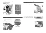
Page 55: ...10 3 CS 53 302 Service Position ...
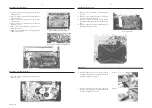
Page 56: ...10 4 CS 53 303 Wiring ...
Page 74: ...D O N O T P R I N T B L A N K P A G E ...
Page 101: ...14 1 14 1 SPR 00 0142 ...


