6-5
6-5
SPR 00 0126
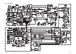
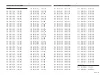
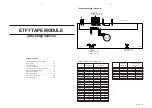
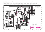
CONTROL PART - CIRCUIT DIAGRAM
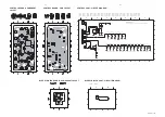
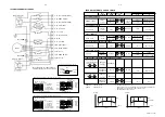
CONTROL BOARD - COMPONENT
LAYOUT
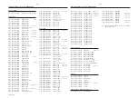
CONTROL BOARD - CHIP LAYOUT
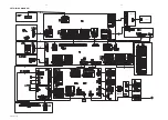
BLUE STRIP LED PART - CIRCUIT DIAGRAM
BLUE STRIP LED BOARD - COMPONENT LAYOUT
This assembly drawing shows a summary of all possible versions.
For components used in a specific version see schematic diagram and respective parts list.
3139 113 3424 pt3 dd wk0035
This assembly drawing shows a summary of all possible versions.
For components used in a specific version see schematic diagram and respective parts list.
3139 113 3424 pt3 dd wk0035
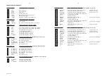
Some location on this board is prepared for both 0603 & 0805 SMDs
footprint, in such locations 0603 SMDs may be substituted.
C
D
1400 A1
1401 A2
1402 C7
1403 C7
1404 C6
1405 B3
1406 B3
1407 B4
1408 B4
1409 B5
1410 C3
1411 C3
1412 C4
1413 C4
1414 C4
1415 C5
1416 C5
1417 C6
1418 C5
1419 C7
1420 A1
2400 B2
2401 B2
2402 B5
2403 C7
2404 C2
3400 C2
3401 D2
3402 A2
&
&
&
&
&
&
&
&
&
&
5.5V
4.8V
1
2
3
4
5
6
7
1
2
3
4
5
6
7
A
B
C
D
A
B
3403 A2
3404 B3
3405 B4
3406 B4
3407 B4
3409 C3
3410 C4
3411 C4
3412 C4
3413 C5
3414 C5
3415 C5
3416 C6
3417 C6
3418 C6
3419 C7
3420 B2
6219 C1
6221 C1
6400 D2
6401 A3
7400 C2
150R
3409
120R
3401
GND-B
1K
3400
GND-B
GND-B
GND-B
GND-B
3420
1K2
1419
DBB
100n
2404
##
##
&
3139 118 53120...87090 for...3424 pt3 dd wk0035
DIM
1413
GND-B
CLOCK
560R
3413
1K2
3415
1416
6401
1N4148
TREBLE_UP
3404
1K8
REC
2K7
3405
1405
2403
100p
1407
1K8
3416
7400
BC847B
GND-B
GND-B
3406
4K7
GND-B
GND-B
10n
2401
1410
PREV
2
TREBLE_DOWN
1406
2402
100p
3417
EH-B
1420
1
BASS_UP
1404
2K7
NEXT
wOOx
1402
BASS_DOWN
1403
1408
3419
10K
3407
GND-B
GND-B
10K
1
3
2
4
MT1
5
MT2
6221
1417
PROG
EC12
1401
4K7
3418
GND-B
3414
820R
SEARCH_UP
1415
3402
10K
1418
6219
3403
SEARCH_DOWN
10n
2400
10K
AUTO_REV
6400
220R
3410
141
1
270R
1412
PLAY
GND-B
GND-B
3411
HSD
GND-B
GND-B
STOP
1414
1409
390R
3412
GND-B
GND-B
GND-B
GND-B
FE-BT-VK-N
1
10
2
3
4
5
6
7
8
9
Key0
+5V6
BlueStrip
1400
Key2
WooxA
+5V6
WooxB
WooxLit
+5V6
+5V6
& : Not for FW-C90.
## : Refer to variation table.
Note : Some values may varies, see respective parts list for correct value.
3139 113 3424 pt3 dd wk0035
This assembly drawing shows a summary of all possible versions.
For components used in a specific version see schematic diagram
and respective parts list.
6229
1
2
1
2
A
A
1000 A1
6229 A2
1000
35022
1
2
3139 118 53120...87400 for...3424 pt3 dd wk0035
Note : Some values may varies, see respective parts list for correct value.
Summary of Contents for FW-P900
Page 20: ...D O N O T P R I N T B L A N K P A G E ...
Page 25: ...4 1 4 1 SET BLOCK DIAGRAM PCS 103 615 Blue Strip wOOx BassTreble ...
Page 44: ...PCS 103 378 9 6 9 6 COMPONENT LAYOUT CHIP LAYOUT 3 4 2 1 6 5 3 4 2 1 6 5 ...
Page 55: ...10 3 CS 53 302 Service Position ...
Page 56: ...10 4 CS 53 303 Wiring ...
Page 74: ...D O N O T P R I N T B L A N K P A G E ...
Page 101: ...14 1 14 1 SPR 00 0142 ...


