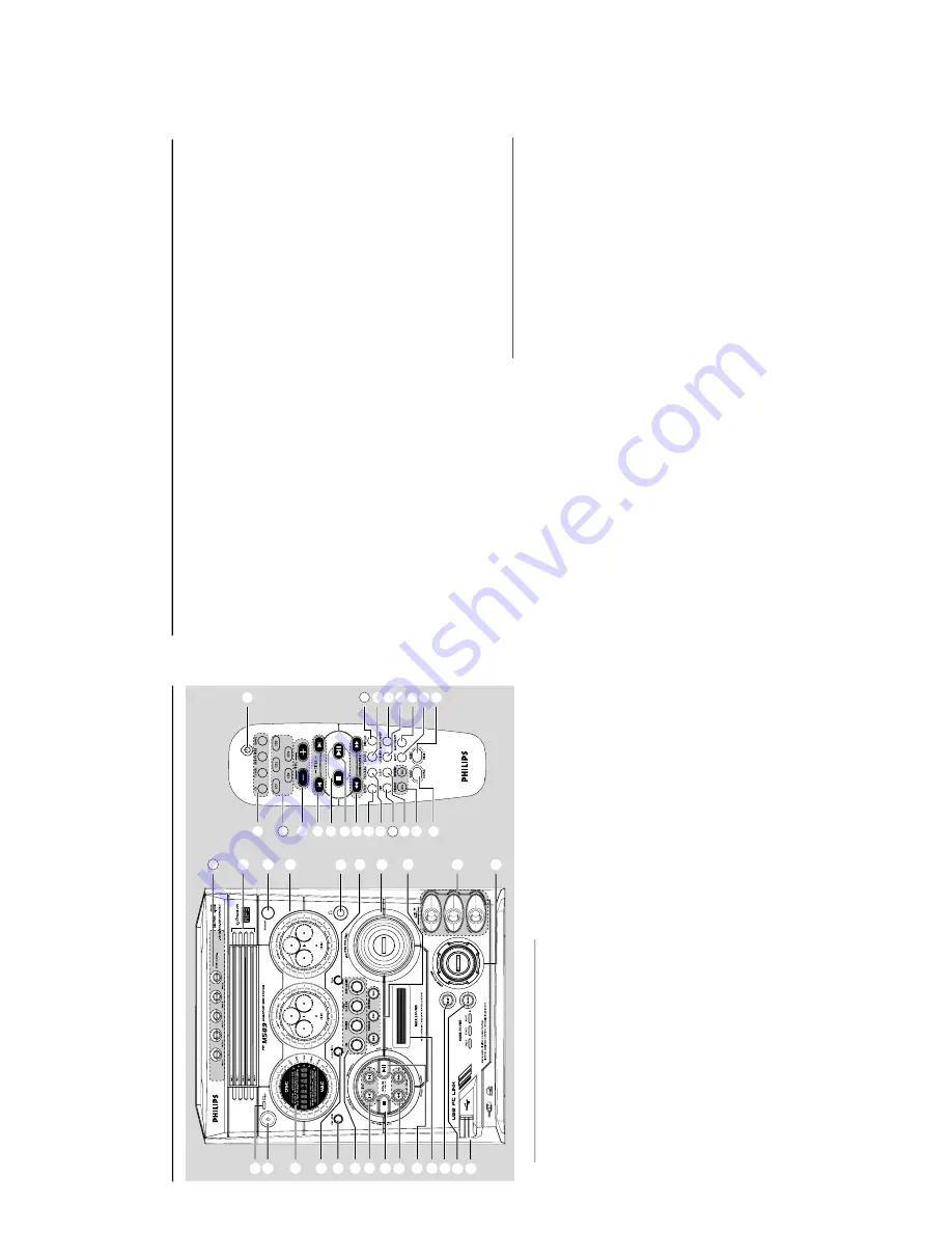
Functional Ov
er
vie
w
Main unit and r
emote contr
ol
1
ECO PO
WER indicator
–
Lights up when the system is in Eco
Po
w
e
r
standb
y mode
.
2
ST
ANDBY ON
B
–S
witches to Eco P
o
w
er standb
y mode or tur
ns
on the system.
–
*Switches to standb
y mode
.
3
Displa
y scr
een
4
CLOCK•TIMER (CLK/TIMER)
–
*Enter
s clock or timer setting mode
.
5
RDS•NEWS
–
In tuner mode
, selects RDS infor
mation.
–
In other modes,
tur
ns on/off news.
6
CD /
TUNER / USB PC LINK
/
A
UX•GAME
–
Selects the relevant acti
ve
m
ode
.
–
CD:
toggles betw
een DISC 1~5.
–
TUNER:
toggles betw
een FM and MW band.
–
A
UX•GAME:
toggles betw
een
A
UX and
GAMEPOR
T mode
.
7
PREV•PRESET
4
(TITLE –) (
í
)
NEXT•PRESET
3
(TITLE +) (
ë
)
–
CD:
selects a tr
ack or selects a title from MP3
disc
.
–
TUNER:
selects a preset r
adio station.
–
CLOCK:
sets the minutes.
–
USB PC LINK:
selects a tr
ack from the pla
ylist.
8
ST
OP•DEMO ST
OP
9
–
Exits an oper
ation.
–
CD:
stops pla
yback or clear
s a progr
amme
.
–
TUNER:
*er
ases a preset r
adio station.
–
USB PC LINK:
stops playback.
(only on the main unit)
–*
Tu
rns on/off the demonstr
ation mode
.
9
SEARCH•TUNING (ALB
UM/PLA
YLIST
43
)
(
àá
)
–
CD:
*searches backward/f
orward or selects an
alb
um from MP3 disc
.
–
TUNER:
tunes the r
adio frequency up/do
wn.
–
CLOCK:
sets the hour
s.
–
USB PC LINK:
Select y
our desired playlist.
* = Pr
ess and hold the button for mo
re
than two seconds
.
⁄
º
4
!
ª
@
‹
§
(
•
&
#
7
6
*
8
0
9
ST
A
N
D
BY
O
N
M
P
3
£
™
¡
)
(
*
&
^
%
1
2
3
4
5
6
!
@
#
$
7
0
9
8
25
27
24
32
0
PLA
Y•P
A
USE
ÉÅ
–
CD:
star
ts/pauses playback.
–
USB PC LINK:
star
ts/pauses pla
yback.
(only on the main unit)
–
TUNER:
*enter
s Plug & Pla
y mode and/or star
ts
preset r
adio station installation.
!
MAX SOUND (MAX ON/OFF)
–T
ur
ns on/off the optimal mix of var
ious sound
features.
@
MIX IT (GAME MIX IT
)
–M
ix
es the game sound with your fa
vour
ite musi
c
from one of these m
usic sources (CD
, TUNER,
USB PC LINK or
A
UX).
#
MODE (GAME SOUND)
–
Selects diff
erent type of equaliser setting fo
r
Gamepor
t (SPEED
, PUNCH or BLAST).
$
Connect the USB cab
le between the system and
PC’
s USB por
t.
%
GAME V
OLUME
–
Adjusts the game’
s output v
olume lev
el.
^
VIDEO
–
Use a video cab
le to connect to y
our game
console’
s video output.
A
UDIO L.
/
A
UDIO R.
–
Use an audio cab
le to connect to y
our game
console’
s left/r
ight audio output.
&
DBB
–
Selects diff
erent type of bass boost le
ve
l settings
(DBB 1, DBB 2, DBB 3 or DBB OFF).
DSC/PRESET
–
Selects diff
erent type of preset sound equaliser
settings (OPTIMAL,
JAZZ,
R
OCK or POP).
VA
C/REVERB
–
Selects diff
erent type of ambience-based
equaliser settings (HALL,
CINEMA,
CONCER
T,
CYBER or
ARC
ADE).
•
PRESET and REVERB en
vironment sound
modes are only a
vailable when the optional
software
, Philips Sound
Agent 2 is activated
dur
ing USB PC Link application.
Functional Ov
er
vie
w
* = Press and hold the button for mo
re
than two
*
MASTER
V
OLUME (V
OL + –)
–
Adjusts the v
olume lev
el.
(
PR
OG (PR
OGRAM)
–
CD:
star
ts or conf
ir
ms tr
acks progr
amming.
–
TUNER:
star
ts *automatic/manual preset
progr
amming.
–
CLOCK:
selects 12- or 24-hour clock displa
y.
)
n
–P
lug in the headphones jack.
The speak
er
s
output will be cancelled.
¡
VU meters
–
Indicates signal strength of left/r
ight channel.
™
iR SENSOR
–P
oint the remote control to
wards this sensor
.
£
Disc tra
ys (1~5)
OPEN•CLOSE
0
(DISC 1~5)
–O
pens/closes the respecti
ve
disc tr
ay
.
Contr
ol buttons a
vailable on the
re
mote contr
ol onl
y
CD 1~5
–
Selects a disc tr
ay to pla
yback.
§
REPEA
T
–
Repeats a tr
ack/disc/all progr
ammed tr
acks.
DIM
–T
ur
ns on/off the dim mode
.
•
SLEEP
–
Sets the sleep timer function.
ª
MUTE
–M
utes or restores the
vo
lume
.
º
TIMER ON/OFF
–T
ur
ns on/off the timer function.
⁄
SHUFFLE
–T
ur
ns on/off the r
andom pla
y mode
.
DISPLA
Y
–D
ispla
ys the album and title name f
or MP3 disc
.
‹
B
–S
witches to Eco P
o
w
er standby mode
.
–
*Switches to standb
y mode
.
.
seconds
1-9
Summary of Contents for FW-M589
Page 16: ...Service position A Service position B Service position C 2 4 2 4 DISMANTLING INSTRUCTIONS ...
Page 62: ...9 2 9 2 AF12 BOARD COMPONENT LAYOUT ...
Page 63: ...9 3 9 3 AF12 BOARD CHIP LAYOUT MAPPING AF12 BOARD COMPONENT LAYOUT MAPPING ...
Page 64: ...9 4 9 4 AF12 BOARD CHIP LAYOUT ...
Page 76: ...10 8 Location of switches ...
Page 84: ...10 16 10 16 Exploded view 5DTC mechanic for orientation only ...


