Mechanical instructions
GB 22
FTV1.9EE
4.
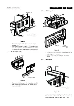
4.1.6
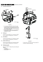
AUDIO VIDEO BUFFER panel.
Figure 4-9
1.
First remove the adjacent SUPPLY panel. This can be
done by removing the 2 fixation screws [1] and lifting this
panel from its bracket [2]. Rotate this panel in such a way
that the copper side is positioned (in an electrical safe way)
aside of the Receiver Box [3].
2.
Now the copper side (SMD or A-side) of the AV-BUFFER
panel becomes accessible. All service test points are
positioned on this A-side.
4.1.7
NICAM panel.
This panel can be checked via the I/O connector on the SSP.
For service properties (exchanging parts) see chapter 2.2.
4.1.8
FEATURE BOX.
This panel can be checked via the I/O connector on the SSP.
For service properties (exchanging parts) see chapter 2.2.
4.1.9
DOUBLE WINDOW panel.
This panel can be checked via the I/O connector on the SSP.
For service properties (exchanging parts) see chapter 2.2.
4.2
Exchanging parts
Some parts of the FTV1.9 Receiver Box must be exchanged if
defective:
•
NICAM panel
•
DOUBLE WINDOW panel.
•
FEATURE BOX.
Figure 4-10
All these panels can be lifted from the SSP by releasing the 2
connector slots sidewards while lifting.
CL96532069_129.EPS
090899
AV-Buffer
2
1
1
3
CL96532069_123.EPS
110899
1
1
2
NICAM
Feature Box
Double Window
Summary of Contents for FTV1.9EE
Page 45: ...Electrical diagrams and print layouts 45 FTV1 9EE 7 Teletext component side ...
Page 46: ...Electrical diagrams and print layouts 46 FTV1 9EE 7 Teletext copper side ...
Page 49: ...Electrical diagrams and print layouts 49 FTV1 9EE 7 Euro I O panel ...
Page 50: ...Electrical diagrams and print layouts 50 FTV1 9EE 7 Euro I O panel ...
Page 51: ...Electrical diagrams and print layouts 51 FTV1 9EE 7 Euro I O component side ...
Page 52: ...Electrical diagrams and print layouts 52 FTV1 9EE 7 Euro I O copper side ...
Page 54: ...Electrical diagrams and print layouts 54 FTV1 9EE 7 Feature box component side ...
Page 55: ...Electrical diagrams and print layouts 55 FTV1 9EE 7 Feature box copper side ...
Page 56: ...Electrical diagrams and print layouts 56 FTV1 9EE 7 Incredible sound Incredible sound ...
Page 57: ...Electrical diagrams and print layouts 57 FTV1 9EE 7 ECO NICAM ...
Page 74: ...Electrical diagrams and print layouts 74 FTV1 9EE 7 Personal notes Personal notes ...


