


Circuit Descriptions, Abbreviation List, and IC Data Sheets
9.
Advantages:
•
Flexibility.
•
No change in internal ROM (IROM) required (IROM not
used).
•
Flexibility to change of code flash manufacturer as the
"flash driver" is part of the bootstrap code (part of the main
software image).
9.11.3
Concept
Figure 9-14 Memory diagram (initial situation)
The architecture of the OTC microprocessor does not allow the
execution of code from the external RAM. It is also impossible
to write data in the code memory space (there is no instruction
to write data to those memory locations).
The OTC normally boots from its internal ROM (IROM) but
modification of the internal ROM software would be too
expensive. Fortunately, the chip architecture allows also the
booting from external ROM (XROM).
The IROM is mapped on the first 32 kB of the ROM address
space. The XROM is mapped starting at the same address.
Therefore, the lower 32 kB of XROM overlaps the IROM
memory space.
Via an external pin (EA), it is possible to reveal the XROM
memory below the IROM and so boot using this hidden
software. This is the first trick used by the software upgrade
procedure.
To be able to write to the CODE flash, it is required to address
the device via the RAM address space. Today all RAM but also
the EPG flash is mapped on the RAM address space.
Devices are mapped to the right address space via a few
control lines (kind of chip select). By exchanging the control
lines between the EPG and the CODE flash, it is possible to
map the CODE flash in the RAM address space and at the
same time use the EPG flash to execute software. This is the
second trick used by the procedure.
The main idea is to use the EPG flash to boot up the software
upgrade procedure.
Therefore, the complete procedure relies on the presence of
that one.
Figure 9-15 Memory diagram (after bus exchange)
In order to be able to write new software code to the set, we
therefore must copy the bootstrap code to a free memory area
(e.g. the EPG flash-memory) in order to be able to execute
"externally" the upgrade procedure code.
Solution: swap the software code to the data memory space
(via setting jumper/switch 1402) and boot from the EPG
FLASH.
After the zip-file uploading and (internally) software unpacking,
the old situation must be restored.
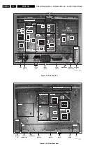
Figure 9-16 Software upgrade set-up
A jumper/switch on the SSP will swap the devices and boot
"externally" via the EPG flash. Then, via ComPair, the
download command is given. The new (ZIP) image will be first
downloaded to the OTCs external RAM (TXT DRAM). Then a
checksum on the ZIP image will be computed on both sides
(PC and TV) and compared.
If everything is correct, the CODE flash will be erased and the
new image will be transferred and unzipped (= decompressed)
into the flash. This is done via the bootstrap code. A second
checksum will be computed on the decompressed image.
After the upgrade, the EPG flash will be cleared again.
CL 36532008_117.eps
130503
Data Memory Space
XRAM (2MB)
0x800000
0x400000
EPG
0x000000
0x3F8000
0x000000
EPG FLASH (512k)
Copy
Code Memory Space
XROM-FLASH (4MB)
OTC DRAM and SRAM
Lower 32k of EPG flash
Bootstrap
SW image (32k)
Bootstrap SW
CL 36532008_118.eps
130503
Data Memory Space
XRAM (2MB)
0x800000
0x400000
0x000000
0x000000
Code Memory Space
XROM-FLASH (4MB)
OTC DRAM and SRAM
Lower 32k of EPG flash
(bootstrap)
EPG FLASH (512k)
Exchange
CL 36532008_116.eps
060503
2MB
4MB
ARTISTIC
(OTC)
TXT
DRAM
7007
7006
SWITCH
7018/7019
0.5MB
EPG
FLASHRAM
ROM/
FLASH-RAM
JUMPER
1402
I
2
C
EA
RAM
CONTROL
ROM
CONTROL
7012
7001
I ROM