


Circuit Descriptions, Abbreviation List, and IC Data Sheets
9.
•
The Eagle delivers a clock signal for the FALCONIC and
the field memories.
•
The Eagle delivers a 64MHz clock to the EBILD (CLK64).
9.7.4
Sync Flow 3fH input sync signals
3fH Sync Signals
•
The input signals do not come via the HIP and PICNIC but
via the AD9883A. This AD converter delivers H and V sync
signals to the EBILD (H-2FH-AD-OUT and V-2FH-AD-
OUT).
•
The sync signals are the same as with 2fH inputs.
3fH Clock Signals
•
The master clock is delivered by the AD9883, same as 2fH
inputs; The EBILD uses this clock as sample clock for
video control.
9.8
Control
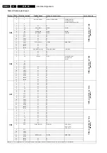
Figure 9-12 OTC interfacing
9.8.1
"Switch On" Behaviour
See paragraph "Power States" in this chapter.
9.8.2
OTC Flash
See paragraph "Software Upgrading" in this chapter.
9.8.3
Keyboard
The local keyboard is connected to P2-4 (pin 107) of the OTC,
which is an A/D pin. Each key matches with a range of values
within the A/D converter.
9.8.4
LED Control
In USA the same LED configuration is used as in Europe, the
2 colour LED.
Table 9-7 LED control
9.9
Protections
9.9.1
General
Under certain fault conditions, as described below, the set must
go into the "protection state". This means that the set is
switched into standby and displays a blinking LED. These
protections are introduced in order to avoid unacceptable
temperature rises and burning hazards. The failure cause will
be identified and put into the NVM error buffer. For the
customer, it is made impossible to switch "on" the set with his
remote control.
On the other hand, it must be possible to read out the error
codes from NVM while using a Dealer Service Tool or a
ComPair tool, or to de-activate the protection states in Service
Default Mode. It is possible to enter ComPair from protection
but not from standby.
The protection algorithms are activated/de-activated at a
certain stage in the "start-up/switch-off" sequence of the set
(see also figure "Step wise start-up diagram" in chapter
"Service Modes, Error Codes, and Fault Finding").
9.9.2
Hardware protections
See also the chapter Service Modes, Error Codes and Fault
Finding of this manual.
Protections with detection via I/O lines of the OTC
8V protection
The +8V information is an ADC input of the microprocessor.
This input can sense the absence of the +8V. The failure is
filtered by software and put in the error buffer for serviceability.
The set must go into protection.
5V protection
The microprocessor can sense the absence of the +5V. The
failure must be filtered by software and put in the error buffer
for serviceability. The set must go into protection.
Because of the architectural set-up of the power supply (the
+5V supply is linked to the +5V2 standby supply of the OTC), it
is not possible to detect a complete absence of the +5V and to
signal it in software. Therefore, no software error indication will
be available when there is a complete short circuit of the +5V
supply.
What happens is this:
•
When the +5V_SW is overloaded (short circuit), this will
also overload the +5V2. The supply that feeds the OTC, the
standby supply, hiccups. As a result, the +5V2 is not
overloaded anymore and can rise again. Because of the
dip in the OTC supply voltage, the OTC will get a reset and
restarts the set. If the fault cause is still present at that start-
up, the system will restart all over and the set will be in a
hiccup mode. This is not a problem if the duty cycle is low
enough.
•
If however, the short circuit on the +5V is such that the
+5V2 supply is not overloaded and the remaining voltage
on the +5V2 is still high enough to keep the OTC alive, the
short circuit on the +5V can be detected via the ADC input
CL 36532053_075.eps
180703
ON-OFF LED L = Red LED ON
STANDBY H= ST-BY
Degaussing = Active Low
Sound Enable active Low (H= Mute)
PWM backlights
SEL-IN2
HD@HOME to HOP (active H)
P50 Out to pin 10 SCART2
Reset -Audio to MSP
Protection s8V (err 5)
Protection s5V (err 4)
Light sensor
SAM Service Mode (active Low)
RGB Blending
Frame
SEL-IN-1
Front Detect (Headphone Detection)
Program-FPGA
OTC
SAA
5801
103
104
113
93
115
117
120
94
95
81
77,78,79,80
116
118
100
96
97
119
110
109
108
107
105
106
5
83,8
74
99
98
114
Audio I/O Selector LSB
Audio I/O Selector MSB
SDM Service Default (active Low)
CVBS TXT
H / V
RESET
P50 IN from pin 10 Scart 2
Audio protect
RC5/RC6 IR receiver
POR Flash
Keyboard
Status SCART4
Status SC3 pin 8
Condition
Two colour LED
On
Green
Off
No indication
Low power standby
No indication
Standby
Red
Semi-standby
Orange (red and green)
Reaction on RC in On-state
Orange (green and (red blinking))
Reaction on RC in Standby
Red
Reaction on RC in Semi-standby
Orange (green and (red blinking))
Protection
Red blinking