


Service Modes, Error Codes, and Fault Finding
5.
5.4.3
Stepwise Start-up
Under normal circumstances, a fault in the power supply, or an
error during start-up, will switch the television to protection
mode. ComPair can take over the initialisation of the television.
In this way, it is possible to distinguish which part of the start-
up routine (hence which circuitry) is causing the problem.
In sets with the Muppet IC present (dual screen functionality),
step 2 is skipped.
Take notice that the transition between two steps can take
some time, so give the set some time to reach a stable state.
During the transition time the LED can blink strangely.
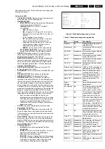
Stepwise start- up explanation
This is realised via ComPair and is very helpful when a
protection is activated (see also chapter “Protections”).
Table 5-2 Stepwise start-up table
Note (*):
•
When the set is in stepwise mode and, due to stepping-up,
a protection is activated, the set will really go into protection
(blinking LED). The set will not leave the stepwise-mode
however. If state X is the state where the set went to
protection, stepwise start-up will return to state X-1. At
state (X-1) diagnostic measurements can be performed.
Also, in the short time the set is in state X but not yet in
protection, you can also do some measurements.
•
Due to the initialisation process of the Muppet IC, step 2 is
not available in sets with Muppet. In this case, step 2 and
3 become one step
5.4.4
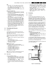
How To Connect
1.
First, install the ComPair Browser software (see the Quick
Reference Card for installation instructions).
2.
Connect the RS232 interface cable between a free serial
(COM) port of your PC and the PC connector (marked with
“PC”) of the ComPair interface.
3.
Connect the mains adapter to the supply connector
(marked with “POWER 9V DC”) of the ComPair interface.
4.
Switch the ComPair interface “OFF”.
5.
Switch the television set “OFF” with the mains switch.
6.
Connect the ComPair interface cable between the
connector on the rear side of the ComPair interface
(marked with “I
2
C”) and the ComPair connector at the rear
side of the TV.
7.
Plug the mains adapter in a mains outlet, and switch the
interface “ON”. The green and red LEDs light up together.
The red LED extinguishes after approx. 1 second while the
green LED remains lit.
8.
Start the ComPair program and read the “Introduction”
chapter.
Figure 5-2 ComPair Interface connection
5.4.5
How To Order
ComPair order codes (EU/AP):
•
Starter kit ComPair32/SearchMan32 software and
ComPair interface (excl. transformer): 3122 785 90450.
•
ComPair interface (excluding transformer): 4822 727
21631.
•
Starter kit ComPair32 software (registration version): 3122
785 60040.
•
Starter kit SearchMan32 software: 3122 785 60050.
•
ComPair32 CD (update): 3122 785 60110.
•
SearchMan32 CD (update): 3122 785 60120.
•
ComPair interface cable: 3122 785 90004.
•
ComPair firmware upgrade IC: 3122 785 90510.
•
Transformer Europe: 4822 727 21632.
•
Transformer UK: 4822 727 21633.
5.5
Error Codes
5.5.1
Introduction
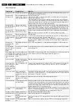
The error code buffer contains all detected errors since the last
time the buffer was erased. The buffer is written from left to
right, new errors are logged at the left side, and all other errors
shift one position to the right.
When an error has occurred, the error is added to the list of
errors, provided the list is not full or the error is a protection
error.
When an error occurs and the error buffer is full, then the new
error is not added, and the error buffer stays intact (history is
maintained), except when the error is a protection error.
To prevent that an occasional error stays in the list forever, the
error is removed from the list after 50+ operation hours.
When multiple errors occur (errors occurred within a short time
span), there is a high probability that there is some relation
between them.
5.5.2
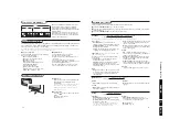
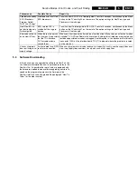
How to read the Error Buffer
Use one of the following methods:
•
On screen via the SAM (only if you have a picture).
Examples:
–
0 0 0 0 0: No errors detected
–
6 0 0 0 0: Error code 6 is the last and only detected
error
–
9 6 0 0 0: Error code 6 was first detected and error code
9 is the last detected error
State Description mode
Display
LED
Enabled
protection
0
Low power standby: 5V2/3V3
present, uP in standby-mode
On
None
1
High power Standby: TV-set
in standby-mode
Wait 1s,
flash 1 x
None
2
Main Power On: HOP in
standby, 5V/8V present, I2C
protections on, SSB is pow-
ered by standby-supply (5V/
8V). Degaussing (12 s) has
been activated, MSP is reset.
Wait 1s,
flash 2 x
4 & 5
3
Initialized (Semi standby):
most IC's are initialized, HOP
still in standby
Wait 1s,
flash 3 x
Plus 1, 6 &
18
4
HOP: HOP fully powered and
working, EHT is present, rest
of IC's initialized, black cur-
rent stabilisation is off, picture
is still blanked
Wait 1s,
flash 4 x
Plus 2 & 16
5
On: TV-set operates, black
current stabilisation is on, pic-
ture is unblanked.
Wait 1s,
flash 5 x
CL96532156_029.eps
190600
PC
VCR
I2C
Power
9V DC
R
L
AUDIO
EXTERNAL 1
EXTERNAL 2
SERVICE
CONNECTOR


