


Mechanical Instructions
4.
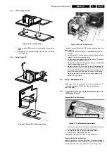
4.2.3
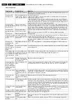
LSP Component side
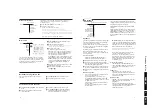
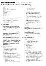
Figure 4-4 LSP unlock action.
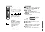
1.
Make sure the SSB bracket is unlocked and placed on the
table.
2.
Release the LSP bracket locking clips and pull it out of the
mounting holes.
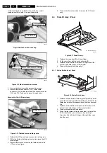
4.2.4
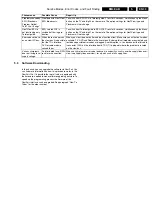
Solder Side LSP
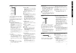
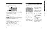
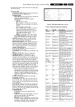
Figure 4-5 Place LSP in Service position.
Figure 4-6 Service position LSP.
For better accessibility of the LSP, do the following (see also
figure above):
1.
Make sure the DAF module is uncoupled from the LSP
bracket.
2.
Unlock both LSP fixation clamps and pull it backwards to
release it out of the mounting holes.
3.
To disconnect the degaussing coil from the LSP, remove
the cable from connector 1502 [1].
4.
Release the wiring from their fixation clamps, in order to get
room for repositioning the LSP.
5.
Replace the two IDE flat cables by the IDE extended flat
cable service set, (48 cm, 40 fold), no: 3104 311 05501.
6.
Rotate the LSP 90 degrees clockwise [2], and place it in
one of the bottom fixation holes as shown in the figure.
7.
Hook the bracket in the first row of fixation holes of the
bottom tray, see figure.
4.3
Assy / PWB Removal
Sometimes, it can be necessary to swap a complete assy or
Printed Wiring Board (PWB). How that can be done is
explained below.
4.3.1
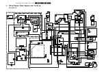
Top Control Panel assy, Display Motor Mechanism, and
LCD Display Removal
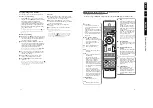
Remove the Top Panel assy:
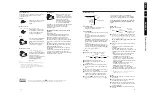
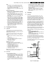
Figure 4-7 Top Panel mounting screws.
1.
Disconnect both cables, which connect the Top Cover assy
to the chassis and remove this Top Cover assy.
2.
Unscrew both Top Panel assy mounting screws.
3.
Grip the assy at both sides and lift it.
4.
Disconnect the cable and take out the panel assy.
Remove the motor mechanism:
Note: To prevent micro switch damage, it is recommended to
remove both micro switch mounting screws before removing
the motor mechanism assy. Take extra care during micro
CL 36532008_010.eps
040403
2
1
1
2
CL 36532008_011.eps
040403
3
1502
1
2
CL 36532008_017.eps
070503
CL36532008_1
Top panel mounting screws


