Circuit Descriptions and Abbreviation List
9.
When the Main DC voltage will decrease w.r.t. the reference
voltage V
BAT
, the 'SUP_ENABLE' line will be activated via
TS7505, TS7508 and R3559. This will switch 'off' the Main
supply via TS7529.
Switch to 'On' (via 'SUP-ENABLE')
Via the 'STANDBY' command from the OTC, the MOSFETS
7141 and 7131 (diagram A2) are switched 'on.' When the OTC
senses the +5V and +8V, a command is given to the HOP to
start the drive (via I
2
C.)
When this is sensed via the 'SUP-ENABLE' line (at the base of
line transistor TS7421, diagram A3), the main supply is
switched 'on' via TS7529 (diagram A1.)
Protection
When, for any reason (interruptions or defective components),
the feedback loop of the Main supply will fail, the V
BAT
will rise.
This is detected via zener diodes D6507, D6508, and D6513.
This will 'ignite' thyristor T7503, which will result in the blowing
of fuse 1503.
Audio Supply
The pulses on the secondary winding of L5506 (or L5512) are
rectified by D6535 (+16 V) and D6536 (-16V), and smoothed by
C2542 and C2543.
9.4
Control (Diagram B5)
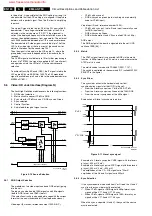
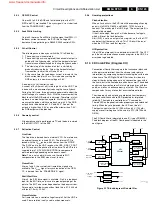
Figure 9-9 Microprocessor (OTC)
9.4.1
OTC
Introduction
The SAA5801 (IC7001) is called the OTC (OSD, TXT/CC, and
Control.) In this IC, the microprocessor and the CC-decoder
are integrated.
Some of its functions are:
•
Set control.
•
CC/OSD acquisition.
•
RGB-outputs to the HOP
•
Menu blending; for blending the contrast, software
controlled.
•
I/O-ports for I
2
C, RC5/RC6, LED, and service modes.
•
Error code generation.
Data Storage
•
The software is 2 MB (Megabytes), and is stored in IC7006.
•
IC7007 is a DRAM of 4 Mbit and this IC is used to store
data of a working set.
•
The Non Volatile Memory IC7011 is a 4 kB version
M24C32W6.
Power Supply
All ICs in this part are supplied with 3V3. For this voltage, a 3V3
stabilizer is used (IC7005.)
With the circuitry around TS7003 and 7004 (diagram B5), a
reset is generated to wake up the OTC (pin 74.) During this
reset, all I/O pins of the OTC are made 'high.'
Via pins 105 and 106, the +8 V and the +5 V are sensed. If one
of them is not present, the Main supply is switched 'off' (set
goes into protection mode, and the red LED blinks at 3 Hz.)
The OTC will generate an error code to indicate the problem.
OSD/CC
The horizontal (H
D
) and vertical (V
SYNC
) sync pulses are also
fed to the OTC for stable OSD and CC.
The RGB-outputs (77/78/79) together with fading (pin 80) are
fed to the HOP. The fading pin has a double function: it is used
for making a transparent menu and as a fast-blanking signal for
CC.
9.4.2
I
2
C Bus
There are three I
2
C busses used:
•
Slow (max. 100 kHz) hardware I
2
C-bus, called I
2
C1, used
for the Tuner.
•
Fast (max. 400 kHz) hardware I
2
C -bus, called I
2
C2, used
for all ICs.
•
Separate short bus, called I
2
C3, for the Non Volatile
Memory (NVM), to avoid data corruption.
9.4.3
NVM
The Non Volatile Memory contains all set related data that must
be kept permanently, such as:
•
Software identification.
•
Operational hours.
•
Error-codes.
•
Option codes.
•
All factory alignments.
•
Last Status items for the cu a complete factory
recall.
9.5
Tuner & IF (Diagram A8 and B2)
The tuner/splitter is I
2
C controlled, and is capable of receiving
off-air and cable channels.
The tuning is done via I
2
C. The reference voltage on pin 9 is 33
V. This voltage (V
TUN
) is derived from the secondary side of the
standby supply, via D6110 and R3116//R3115 and a 33 V
zener diode (D6200.) The OTC, together with the HIP, controls
the tuning procedure. There is also automatic switching for the
different video systems.
The IF-filter is integrated in a SAW (Surface Acoustic Wave)
filter. The type of this filter depends on the received
standard(s.) There are two SAW filters: one for filtering picture-
IF and a second one for sound-IF.
The output of the tuner is controlled via an IF-amplifier with
AGC-control. This is a voltage feedback from pin 62 of the HIP
to pin 1 of the tuner. AGC take-over point is adjusted via the
service alignment mode 'Tuner AGC.' If there is too much noise
CL 26532041_063.eps
110402
SAA5801
P50-OUT
SEL_IN_2
STATUS SC3
FRONT DETECT
120
A0...A19
D0...D15
CVBS-TXT
7001
5
KEYBOARD
107
+5V
106
+8V
105
+3V3
113
+5V2
RESET
ON/OFF-LED
74
H, V
83,84
119
117
109
LIGHT SENSOR
110
DEGAUSSING
115
108
SEL_IN_1
103
STANDBY
104
POR
99
RC5/RC6
100
P50-IN
97
SDM
4006
96
SOUND ENABLE
95
RESET AUDIO
94
RGB, BLENDING
77,78,79,80
87/88
91/92
FRAME
81
FLASH
EPG
FLASH
(SW)
DRAM
(TXT)
TUNER
SAM
4005
+3V3 +
RESET
+3V3
+3V3
I2C2
I2C1
85/86
slow
NVM
I2C3
fast
HIP
HOP
MSP
FBX
TOPIC
NVM
(PROG)
WIRELESS EXPANDER
WIRELESS TRANSMITTER
3D COMBFILTER
DVD ENGINE
MOIRÉ EXPANDER
AUTOSCAVEM DAC
DVD INTERFACE EXPANDER
PIP I/O EXPANDER
BOCMA PIP
SfH I/O EXPANDER
Vchip PIP
www.freeservicemanuals.info
Summary of Contents for EM5A NTSC
Page 6: ...Direction for Use EN 6 EM5A NTSC 3 3 Direction for Use www freeservicemanuals info ...
Page 7: ...Direction for Use EN 7 EM5A NTSC 3 www freeservicemanuals info ...
Page 8: ...Direction for Use EN 8 EM5A NTSC 3 www freeservicemanuals info ...
Page 9: ...Direction for Use EN 9 EM5A NTSC 3 www freeservicemanuals info ...
Page 10: ...Direction for Use EN 10 EM5A NTSC 3 www freeservicemanuals info ...
Page 11: ...Direction for Use EN 11 EM5A NTSC 3 www freeservicemanuals info ...
Page 12: ...Direction for Use EN 12 EM5A NTSC 3 www freeservicemanuals info ...
Page 13: ...Direction for Use EN 13 EM5A NTSC 3 www freeservicemanuals info ...
Page 14: ...Direction for Use EN 14 EM5A NTSC 3 www freeservicemanuals info ...
Page 15: ...Direction for Use EN 15 EM5A NTSC 3 www freeservicemanuals info ...
Page 16: ...Direction for Use EN 16 EM5A NTSC 3 www freeservicemanuals info ...


