


Electrical Alignments
8.
8.
Electrical Alignments
Index of this chapter
1.
General alignment conditions
2.
Hardware alignments
3.
Software alignments
4.
Option settings
8.1
General Alignment Conditions
8.1.1
Start Conditions
Perform all electrical adjustments under the following
conditions:
•
Power supply voltage: 120V
AC
/230 V
AC
(
±
10 %), 50/60 Hz
(depending on the set type).
•
Connect the set to AC power via an isolation transformer
with low internal resistance.
•
Allow the set to warm up for approximately 20 to 30
minutes.
•
Measure voltages and waveforms in relation to chassis
ground (with the exception of the voltages on the primary
side of the power supply.)
Caution: never use heatsinks as ground.
•
Test probe: Ri > 10 Mohm, Ci < 20 pF.
•
Use an isolated trimmer/screwdriver to perform
alignments.
Perform all electrical adjustments with the following start
settings (for all CRTs):
•
Set LIGHT SENSOR “off”, by setting ACTIVE CONTROL
“off” with the remote control transmitter.
•
Set CONTRAST to 100, BRIGHTNESS to 31 and COLOR
to 51(via PICTURE menu.)
•
Set COLOR ENHANCEMENT to “off” (via PICTURE
menu.)
•
Set DIGITAL PROCESSING to 'Pixel Plus' (via PICTURE
menu), unless otherwise stated (for sets without 'Pixel Plus'
(Eagle), set to 'Natural Motion'.)
•
Set DYNAMIC CONTRAST to “off” (via PICTURE menu.)
•
Set CATHODE DRIVE at 15 (via SAM - Alignments - Drive
- Cathode.)
8.1.2
Adjustment Sequence
Use the following adjustment sequence:
1.
Set the correct TV set ‘options’ (after storing, re-start the
set.)
2.
Rough adjustment of ‘Vg2’ and ‘Focus.'
3.
Rough adjustment of ‘Geometry.'
4.
Allow the set to warm up.
5.
Precise adjustment of ‘Vg2’ and ‘Focus.'
6.
Precise adjustment of ‘Geometry.'
7.
Software alignments (cut-off, cathode drive, peak white,
white drive, etc.)
8.2
Hardware Alignments
Note: The Service Alignment Mode (SAM) is described in the
'Service Modes, Error Codes and Fault Finding' section. Menu
navigation is performed with the “MENU UP, DOWN, LEFT and
RIGHT” keys of the remote control (RC) transmitter.
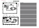
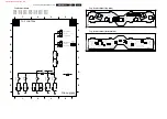
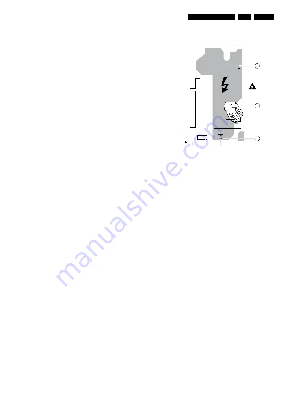
Figure 8-1 Top view LSP
8.2.1
Vg2 Adjustment
Method 1 (with oscilloscope)
In the frame-blanking period of the R, G, and B signals applied
to the CRT, the “HOP” video processor inserts a measuring
pulse with different DC levels. Measure the black level pulse
during the vertical flyback at the RGB cathodes of the CRT.
1.
Use the 'MENU' key to enter the user menu, select
'PICTURE,' and set 'CONTRAST' and 'BRIGHTNESS' to
'0.'
2.
Enter SAM. To enter SAM, press the following key
sequence on the remote control transmitter: 062596
directly followed by 'STATUS/EXIT' (do not allow the
display to time out between entries while keying the
sequence.)
3.
Connect the RF output of a pattern generator to the
antenna input. Input a “black” picture (blank screen on CRT
without any OSD info) test pattern.
4.
Set the oscilloscope to 20 V/div and the time base to 20 us/
div. Use external triggering on the vertical pulse
(caution: use a trigger point on the “cold” side!)
5.
Ground the scope on the CRT panel (”cold” side) and
connect a 10:1 probe to one of the cathodes of the picture
tube socket (see diagram F1.)
6.
Measure the cut-off pulse during first full line after the
frame blanking. You will see two pulses; one is the cut-off
pulse and the other is the white drive pulse. Choose the
one with the lowest value; this is the cut-off pulse.
7.
Select the cathode with the highest V
DC
value for the
alignment. Adjust the V
CUTOFF
of this gun with the SCREEN
(lower) potentiometer on the LOT to the correct DC value
(tolerance is +/- 3 V
DC
): 29" 4:3 = 160 V, 34" 4:3 = 160 V,
and 36" 16:9 = 170 V.
8.
Reset 'CONTRAST' and 'BRIGHTNESS' to normal
(CONTRAST = 100 and BRIGHTNESS = 31.)
CL 26532058_021.eps
0706402
SSB
V.SHIFT
CINCH CINCH
TUNER
3642
1502
5430
Focus 2
Focus 1
Screen
VG2
LOT
Warning
All alignments
are on hot-part !
A
B
C
www.freeservicemanuals.info
Summary of Contents for EM5A NTSC
Page 6: ...Direction for Use EN 6 EM5A NTSC 3 3 Direction for Use www freeservicemanuals info ...
Page 7: ...Direction for Use EN 7 EM5A NTSC 3 www freeservicemanuals info ...
Page 8: ...Direction for Use EN 8 EM5A NTSC 3 www freeservicemanuals info ...
Page 9: ...Direction for Use EN 9 EM5A NTSC 3 www freeservicemanuals info ...
Page 10: ...Direction for Use EN 10 EM5A NTSC 3 www freeservicemanuals info ...
Page 11: ...Direction for Use EN 11 EM5A NTSC 3 www freeservicemanuals info ...
Page 12: ...Direction for Use EN 12 EM5A NTSC 3 www freeservicemanuals info ...
Page 13: ...Direction for Use EN 13 EM5A NTSC 3 www freeservicemanuals info ...
Page 14: ...Direction for Use EN 14 EM5A NTSC 3 www freeservicemanuals info ...
Page 15: ...Direction for Use EN 15 EM5A NTSC 3 www freeservicemanuals info ...
Page 16: ...Direction for Use EN 16 EM5A NTSC 3 www freeservicemanuals info ...