Electrical diagrams and Print-layouts
42
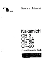
DVD 950
6.
A/V board
DRIVER
EN
G1
1
MUX
1~
DRAM
MICOM uF
DSP
IN
DIGITAL
OUT
IN
MIC
IN
TIMING GENE.
OUT
ANALOG
ANALOG
DIGITAL
CONTR
OL
INTERF
A
C
E
DAC’S
VOL/MUTE/DEEMPH
INTERPOL FILTER
NOISE SHAPER
NC
DIGIT
AL
INTERF
A
C
E
F526
A2 : A/V PCB
ONLY FOR KOK VERSION
NOT FOR
4432 K4
4433 K4
4434 K3
4506 D9
5400 K13
I500 I10
I501 G18
I502 H18
I518 B15
I520 C16
I521 D15
I522 D15
I525 A10
I526 B10
I527 B11
I528 C10
I529 D9
I530 E10
I531 G9
I532 G8
I533 G10
I534 I9
I535 G14
I545 H6
I546 G7
I547 G14
I548 H14
I549 G17
I550 H16
I551 G6
F519 B15
F520 L12
F521 L13
F522 L14
F523 L13
F524 N13
F526 E5
F527 E6
F528 K7
F529 K7
F530 K7
F531 K7
F532 K7
I481 L9
I482 L9
I483 L9
I484 M5
I485 M6
I486 N5
I487 N5
I488 N4
I489 N4
I490 N3
I491 N3
I492 D11
I493 E11
I494 G11
I495 I11
I496 G8
I497 E10
I498 G10
I499 H10
F456 C4
F458 F4
F459 E13
F461 A8
F462 A8
F463 C7
F464 C7
F465 A9
F467 A10
F468 A12
F471 B11
F472 C11
F474 C9
F477 C11
F478 C11
F479 E9
F480 F6
F481 F7
F482 H6
F488 F9
F489 F10
F497 I8
F498 I7
F504 F16
F505 F16
F506 F17
F507 F18
F508 H16
F510 H16
F512 H17
F513 H18
F518 K12
7007 N13
7027 B5
7028 B10
7029 B11
7030 D10
7031 D11
7032 F11
7033 G10
7034 H10
7035 I10
7036 G17
7037 G18
7038 H16
7040 H18
7402 B2
7403 C4
7404-A B11
7404-B C8
7404-C A9
7404-D A11
7405-A F8
7405-B E9
7405-C H8
7405-D G7
7406-A F13
7406-B G13
7406-C H13
7407-A F15
7407-B H15
7408 K15
7409 L6
7410 I2
2.8VRMS
VERSION
*
J
K
L
M
N
1002 E16
1003-1 K6
1003-2 K6
1003-3 K6
1003-4 K6
1003-5 K6
1400-A B13
1400-B F12
1400-C H11
1401-B B16
1401-C H20
1404 C16
1405 L15
2406 C8
2430 B2
2431 B3
2432 C3
2433 F4
2434 F4
2435 F5
2436 A6
2437 C6
2438 B8
2439 D8
1
2
3
4
5
6
7
8
9
10
11
12
13
14
15
16
17
18
19
20
1
2
3
4
5
6
7
8
9
10
11
12
13
14
*
**
**
15
16
17
18
19
20
A
B
C
D
E
F
G
H
I
J
K
L
M
N
A
B
C
D
E
F
G
H
I
ONLY FOR
**
2440 A9
2441 C12
2442 C9
2445 C13
2447 E10
2450 D14
2451 D15
2452 E11
2453 E9
2454 E10
2455 F9
2456 F9
2457 G7
2458 H7
2459 G8
2460 G9
2462 G11
2465 H11
2466 I8
2467 I11
2469 M14
2470 I7
2471 F13
2472 F14
2473 F16
2474 F15
2475 G15
2476 H16
2477 I19
2478 I20
*
(3n9)
2479 M3
2480 N4
2481 N4
2482 N5
2483 M5
2484 M5
2485 L6
2486 L7
2487 K9
2488 L12
2489 L12
2490 L14
2491 K15
2492 N12
2496 C8
2497 C15
2498 C15
2507 I2
2624 K8
2625 K8
2627 E16
2628 E16
2629 E16
2630 E16
2631 F16
2639 K8
3480 B5
3481 C5
3482 D14
KOK
3V
*
3483 D14
3484 A6
3485 A6
3486 A6
3487 B8
3488 A10
3489 B9
3490 A10
3491 B11
3492 C12
3493 C6
3494 D6
3495 D6
3496 C9
3497 C10
3498 D8
3499 D9
3500 D10
3501 C13
3502 F7
3503 E7
3504 G7
3505 G7
3506 F9
3507 F9
3508 D9
3509 E10
3510 E11
3511 G11
OPTION
3512 G10
3514 G10
3515 G6
3516 H6
3517 H7
3518 G9
3519 H9
3520 I11
3521 I10
3522 I10
3523 I7
3524 I7
3525 I6
3526 F17
3527 F18
3528 G17
3529 G18
3530 H17
3531 H17
3532 I17
3533 H17
3539 N12
3540 D3
3541 K11
3542 L11
3543 L14
3544 L9
3545 L9
3546 L9
3547 N4
3548 N4
2 STEREO LEFT & RIGHT
6 C 1 STEREO LEFT & RIGHT
*
3549 N5
3550 N5
3551 D3
3552 E13
3553 H11
3554 E10
3555 M14
3563 C14
3564 C15
3565 I19
3566 I20
3573 I3
3574 I3
3575 J3
3692 A12
3693 C11
3694 M12
4413 C4
4414 D5
4415 D5
4416 F4
4417 A12
4418 C12
4419 F19
4420 F14
4421 H14
4422 H19
4431 K4
F456
5
4
+8VAud
5K6
3516
6
22n
2431
1401-B
STEREO_L
STEREO_R
2498
22n
2471
1n
7037
BC817-25
YKC21-4040
1n
I525
10K
3564
3563
10K
220R
3512
2497
I518
5
LM833D
7407-B
PCM_OUT2
PCM_OUT1
CENTER
HP_L
KILL
PCM_CLK
LRCLK
PCM_OUT0
SCLK
3V3A
3V3A
BC817-25
7034
I520
47R
3
2
1
8
4
3493
F519
2435
F527
**
KOK
VERSION
**
*
F465
MC33079
7405-B
5
6
7
4
11
+5V
EH-B
1003-5
5
-8Vstby
+8VAud
47R
3544
3489
2K7
F510
22n
2455
1404
YKC21-3337
1
2
3
I490
I535
2491
100n
+5Va
I492
2631
1n
I545
2629
1n
2630
1n
3552
4R7
10K
3494
I521
4R7
3508
1405
YKC21-3416
1
3
2
4416
F480
3527
100R
WS
11
1n
2452
TST1
27
TST2 22
VDDA
6
VDDD
21
VO1N
29
VO1P
28
VO2N 31
VO2P 32
VO3
1
VO4 2
VO5
4
VO6 5
VREFA
30
VSSA
3
VSSD
20
DEEM0 25
DEEM1 24
DI12
12
DI34
13
DI56
14
DS 26
L3CLK 18
L3DATA
19
L3MODE 17
MUTE 23
7
8
15
STATIC
9
SYSCLK
16
I551
UDA1328T
7403
BCK
10
VD
A2
24
VDD1
42
VDD2
43
VDL
20
VDX
15
VR2
4 VRA1
7 VRA2
21
XI
22
XO
+5V
9 LPFO3
33 LRCKI
30
LRCKO
12
LZ
27 26
2 MIC1
35
RESN
19
RI
18
RZ
31 SDI
28
SDO
41
TEST
1
VD
A1
17
CKS
25
39
EMP
40
EXT
O
10
GND
A1
13
GND
A2
34
GNDD
44
GNDL
23
GNDX
36
IFD
38
IFL
37
IFS
11
LI
3 LPFO1
6 LPFO2
TC9409BF
7409
5 AIL
8 AIR
14
AOL
16
AOR
32 BCKI
29
BCKO
-8Vstby
-8Vstby
4419
3575
47R
3574
47u
+12VAUD
2467
1n
10K
3549
2466
4n7
2481
2447
47u
F529
10
9
14
13
12
15
8
GND
1
VCC
16
-8Vstby
74HCT157D
7410
2
3
4
5
6
7
11
1003-3
EH-B
3
I484
100R
3541
F531
I526
I531
I488
3515
100K
2457
22p
3498
4414
10K
7028
BC817-25
100R
3530
-8Vstby
+5VD
-8Vstby
F458
470p
2451
2432
+5Va
2473
100U
S
16
Vdd
7
Vee
8
Vss
12 Y0
13 Y1
14
Z
-8Vstby
22n
6
4
5
+8VAud
7406-A
HEF4053BT
6
E
11
F506
1400-B
YKC21-4040
47p
I529
4431
2489
F522
4415
F520
F472
47R
3546
3491
2K7
6
7
8
4
F508
I489
F505
2627
1n
2628
1n
1n
2625
3496
100R
10K
1003-2
EH-B
2
4432
I485
3495
GP1F32T
7408
3
1
2
47u
3531
47u
2459
7040
BC817-25
100R
F471
1
2
3
4
5
6
7
I498
EH-B
1002
100K
3503
22n
2486
4433
2465
1n
F462
10K
3501
I487
3V3
3553
10K
22n
2433
2K7
3500
-8Vstby
F479
3490
100R
+8VAud
2K7
3509
-8Vstby
3533
2K7
2453
22n
7404-A
MC33079
3
2
1
4
11
100K
3525
3506
+5VD
22p
2458
5K6
3542
100R
2445
1n
10K
3484
3523
10K
I482
+8VAud
F488
22n
2475
I527
+8VAud
3529
2K7
100R
3526
22n
2406
4417
3551
10K
+12VStby
I494
4u7
2483
3492
10K
I532
+12VAUD
F482
2470
2441
1n
3548
22p
10K
3547
10K
100R
3481
5K6
5K6
3504
3497
4413
I500
F478
3521
220R
7405-C
MC33079
10
9
8
4
11
2K7
3522
3507
2476
100U
+5Va
10K
2485
22n
F497
22n
2487
2490
100n
BC817-25
7038
BC817-25
7036
I530
7035
BC817-25
3480
2K2
F512
10K
3485
3V3
2450
2469
47p
470p
LF33CV
7402
2
GND
1
IN
3
OUT
47u
220R
3518
2496
7406-B
HEF4053BT
6
E
10
S
16
Vdd
7
Vee
8
Vss
2 Y0
1 Y1
15
Z
I486
+5VD
3532
2K7
F498
I533
I496
I546
220n
3543
68R
2434
100n
2430
F481
2477
220p
I528
F513
I534
3511
10K
F507
3V3
F463
BC817-25
7029
I550
100R
3483
F459
10K
3517
I495
3
4
6
7
8
10K
3540
7CHA
5400
1
2
100U
2440
100p
2439
2438
100p
F528
I491
+12VAUD
+5VD
3519
BC817-25
7032
I497
2K7
3524
5K6
F477
1003-1
EH-B
1
2462
1n
+5V
3554
220R
2488
10u
2K7
3528
F523
22K
3550
I548
8
Vss
5 Y0
3 Y1
4
Z
100p
2436
7406-C
HEF4053BT
6
E
9
S
16
Vdd
7
Vee
9
7
8
2454
47u
I481
1400-C
YKC21-4040
I483
-8Vstby
2442
100U
1003-4
4
+5V
F521
5
6
7
4
11
EH-B
-8Vstby
MC33079
7404-B
3693
100R
13
14
4
11
3692
100R
MC33079
7405-D
12
3555
10K
100K
3502
3
1
2
3488
100R
3487
10K
1400-A
YKC21-4040
1
4
11
100p
2437
-8Vstby
+5VD
7405-A
MC33079
3
2
2474
22n
F530
+5V
I499
7030
BC817-25
3505
10K
2507
22n
4506
1n
2639
1n
2624
3499
2K7
+8VAud
-8Vstby
82p
2482
F464
10K
F504
I501
3486
I493
3514
2K7
4422
2460
47u
+8VAud
F489
47R
3573
4434
I522
10K
3520
10K
F524
7407-A
LM833D
7027
BC817-25
I502
3565
10K
47u
2472
10K
3566
1401-C
YKC21-4040
9
7
8
+5V
3482
100R
F468
1K
3694
MC33079
7404-D
12
13
14
4
11
2492
100n
470n
2479
4421
BC817-25
7031
47R
3545
9
8
4
11
7033
BC817-25
+12VAUD
7404-C
MC33079
10
4u7
2484
3n3
2480
-8Vstby
F461
4420
+5V
F518
F467
22p
2456
F532
10K
3510
220p
2478
3539
I547
+5V
47K
I549
4418
BC817-25
7007
F474
STEREO_R
STEREO_MUTE
HP_R
HP_L
CENTER_ON
CENTER
HP_R
HP_L
HP_R
MICRO
MICRO
P50
KILL
KILL
KILL
KILL
ST_L
ST_R
STEREO_L
KILL
DIG_OUT
KILL
ST_L
KILL
ST_R
KILL
KILL
KILL
CL 96532114_013.eps
201099