


Installation & User’s Manual
Vision.net Touchscreens
6
INSTALLATION AND SET UP
INSTALLATION AND SET UP
1. Power Requirements
The Vision.net Touchscreen operates on 27VDC. It is powered through the Touchscreen Control PCB (pre- installed
on the back of the touchscreen) via an external AC to DC power supply.
2. Mounting / Installation
Note:
The Vision.net Touchscreen Control PCB is a card that connects to the touchscreen to allow VN/485 and RS-
232 communications. This card is mandatory for a Vision.net system that is communicating SVN/485 only. The
Touchscreen Control PCB is pre-installed in on the back of the touchscreen.
To install wall-mounted touchsreens:
Step 1. If conduit is required by local code, provide conduit to the back box where the Touchscreen Control PCB is
installed.
Step 2. Install the back box at the desired location.
Step 3. Refer to next section for touchscreen wiring and connections.
3. Wiring and Connections
Connecting Power - Using an External Power Supply
To connect an external power supply (not powering from Vision.net network):
WARNING!
Make sure power is disconnected (removed) before connecting power to touchscreen.
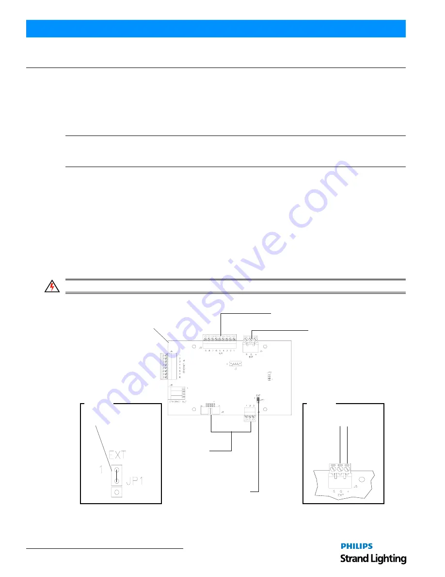
Step 1. As shown in
Figure 3
, at Touchscreen Control PCB make sure jumper at JP1 is on Pins 1 and 2.
Figure 3: Touchscreen Control PCB Jumper Setting and Power Connections
Step 2. Using two (2), #14 AWG (.75 mm2) wires, connect external power supply as illustrated in
Figure 3
.
Touchscreen Control PCB
(located on back of touchscreen)
Black (Common)
Red (+24VDC)
Power Input
(see Detail B)
Detail A
Jumper JP1
(see Detail A)
Jumper
From External
(across Pin 1 and 2)
Power Supply
Detail B
Vision.net LAN
Wiring to
Touchscreen
(factory wired)


