Wiring and Connections
9
Vision.net Touchscreens
Installation & User’s Manual
Network Connections
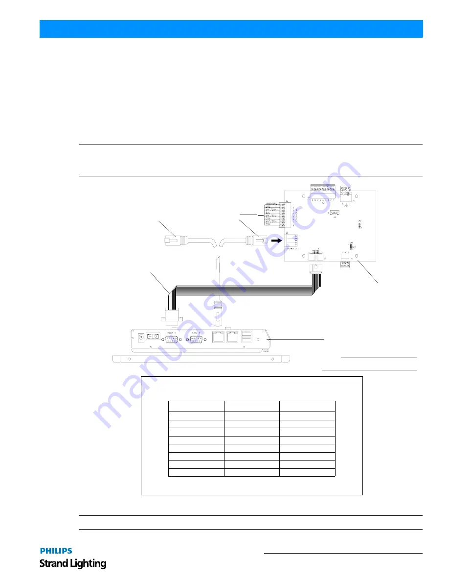
Once the wiring is terminated to the Touchscreen Control PCB, proceed to connecting the touchscreen itself.
There are two connection options:
1) Connect the network cable from the RJ-45 port on the touchscreen to “Ethernet out” RJ-45 port on
Touchscreen Control PCB as shown in
Figure 7
. Connect Ethernet using Belden 1583A cable from the
SNV/IP network on the “Ethernet In” 8-pin connector.
OR
2) Connect a standard CAT5e cable from the SVN/IP network directly to the RJ-45 port on the touchscreen.
Note:
The RJ-45 connections on the Control PCB are for convenience wiring only. It is only a pass through and does
not convert SVN/IP to SVN/485 or SVN/485 to SVN/IP. If the ethernet jack is used, a static IP address in the same
range must be configured for the jack to be active.
Figure 7: Touchscreen Network Connection
Note:
Connect Touchscreen Control PCB to Touchscreen COM Cable if not already connected as shown in
Figure 7
.
Note:
Exploded view shown for clarity.
Touchscreen
Touchscreen
Ethernet Network
(see connection chart)
* Required cable - Belden 1538A
Table 2: Ethernet Wiring Connections*
Pin
Signal
Color
1
RX +
White / Orange
2
RX -
Orange
3
TX +
White / Green
4
Not Used
Not Used
5
Not Used
Not Used
6
TX -
Green
7
Not Used
Not Used
8
Not Used
Not Used
Control PCB
Network Option 1
Ethernet Network
(from SVN/IP network)
Network Option 2
OR
Touchscreen
COM Cable


