background image

OccuSwitch DALI

User Guide

Page 10

2 .1 .2 

OccuSwitch DALI Advanced (LRM208x)

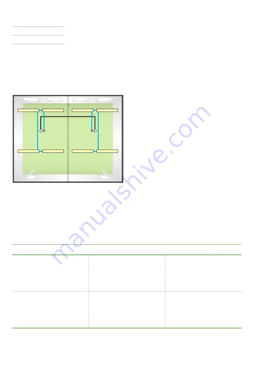
Figure 2: Two grids in one office linked with an OccuSwitch DALI Advanced 

installation

The OccuSwitch DALI Advanced is a module that allows 
covering larger areas such as open plan offices . Up 
to 22 modules can be connected in parallel to create 
lighting zones in an open office . These lighting zones 
can be used, for example, so that the local lights in one 
area are switched on at occupancy and the lights of the 
surrounding areas are automatically set to the background 
lighting level .

Table 5: OccuSwitch DALI Advanced connectors

Example

Figure 2 shows an example with a larger room existing of 
two office grids with each their own OccuSwitch DALI . The 
two devices are connected via parallel linking, so they can 
share their occupancy status with each other . This means 
that when someone enters the office the lights on that side 
will switch on . A message is send to the neighboring unit . 
Depending on configuration, the lights in that area will 
switch on to the normal level or to the background level .

Output connectors

Un-commissioned system

Commissioned system

DALI Output connector “DA”

The system regulates all connected 
luminaires identically . This can cause 
insufficient light further away from the 
window .

Up to four output groups (window 
row, corridor row, plus two additional 
groups) can be set . This allows setting 
correct light levels for all luminaire 
groups .
For commissioning, see chapter 4 .

Parallel link connector “X”

By default the OccuSwitch DALI 
Advanced is set to local occupancy 
(Mode 1) . Once one OccuSwitch DALI 
detects occupancy, all OccuSwitch 
DALI devices on the same parallel link 
will turn their lights on .

It is possible to set other OccuSwitch 
DALI devices using the same parallel 
link to go to background level when 
one OccuSwitch DALI is occupied 
(Mode 9) .

Summary of Contents for 61430036

Page 1: ...User Guide OccuSwitch DALI OccuSwitch DALI ...

Page 2: ...4 2 3 Automatic control 14 2 3 1 Occupancy 14 2 3 2 Daylight Dependent Regulation 15 2 3 3 Local control 16 2 3 4 Infrared group addressing 16 2 3 5 Manual control on IR channels 17 2 3 6 Relation between IR channels and DALI groups 17 2 3 7 Manual control with the IRT8050 18 2 3 8 Local control with standard switches and the LCU2070 19 2 3 9 Presets 20 2 3 10 Local control of multiple OccuSwitch ...

Page 3: ...ecks 31 4 2 2 Hold timer 31 4 2 3 Assigning luminaires to DALI groups 31 4 2 4 Calibration of the required light level 31 4 2 5 100 hour burn in mode 33 4 2 6 Request application mode 33 4 2 7 Mass programming 33 4 2 8 Set application mode 34 4 2 9 Background level 34 4 2 10 Power up state 35 4 2 11 Infrared group address 35 4 3 Reset to factory defaults 36 4 4 Walk test 36 5 OccuSwitch DALI BMS L...

Page 4: ... 39 5 4 3 How to use the combination of OccuSwitch DALI and gateways 39 5 4 4 Cascading DALI network 39 5 4 5 OccuSwitch DALI 39 5 4 6 The gateway 40 5 5 How does the OSD react to DALI commands 41 5 6 DALI grouping and occupancy control 42 5 7 Corridors 43 5 8 Grouping without gateway 43 5 9 Energy measurement 43 5 10 How to commission a OSD with a network 43 5 11 Command list 44 6 Technical Speci...

Page 5: ... automatically turns the lighting in a room on and off based on occupancy When enough daylight natural light enters the room the system dims the luminaires artificial lights OccuSwitch DALI is a combined sensor and controller It has three main functional parts a light sensor for daylight depending regulation a movement detector for occupancy control and an infrared receiver for remote control The ...

Page 6: ...lly extended with an extension sensor Mounting Optimized for recessed ceiling mounting and for mounting heights between 2 5 and 4 meter Application modes 9 available modes to suit different locations Building Management Systems BMS Up to 64 OccuSwitch DALI LRM2090 devices can be linked to standard DALI interfaces Number of extension sensors Maximum number of extension sensors is 2 When connection ...

Page 7: ...s for window and corridor installation LRM2072 OSD Basic NB Exactly like LRM2070 but without the Philips wordmark on the front plate LRM2080 OccuSwitch DALI Advanced Standalone system with 2 DALI output connectors One connector is programmable for the luminaires The other connector forms a parallel link to up to 22 different OccuSwitch DALI systems LRM2082 OSD Advanced NB Exactly like LRM2080 but ...

Page 8: ...CC2080 cable Advanced and BMS Cable for OccuSwitch DALI Advanced systems LRM2080 LRM2082 and OccuSwitch DALI BMS systems LRM2090 and LRM2092 LRH2070 Surface box Box for mounting the OccuSwitch DALI system all types onto the ceiling The box is equipped with mounting holes for standard BESA boxes and socket plates IRT9090 Extended IR programming tool Tool capable of full commissioning Batteries incl...

Page 9: ...he DA output but it also works on the X output Here commissioning allocating luminaires to a specific function is generally required when daylight depending regulation is used Number of connectors in use Un commissioned system Commissioned system 1 DALI output connector DA used Other connector X left open The system regulates all connected luminaires identically This can cause insufficient light l...

Page 10: ...each other This means that when someone enters the office the lights on that side will switch on A message is send to the neighboring unit Depending on configuration the lights in that area will switch on to the normal level or to the background level Output connectors Un commissioned system Commissioned system DALI Output connector DA The system regulates all connected luminaires identically This...

Page 11: ...re 3 shows an example layout of two cell offices Each office part has its own OccuSwitch DALI BMS and two rows of luminaires a window row and a corridor row The OccuSwitch DALI devices are connected to a BMS system Both OccuSwitch DALI BMS systems control the connected lights automatically The BMS system is used to monitor the system and to override the local settings in special situations Connect...

Page 12: ... the movement with its built in movement detection sensor This means that the luminaires are controlled on movement detection in both the main and the extension area The extension movement sensor is ideal for areas such as classrooms that are slightly larger or differently shaped than the standard movement detection area of the OccuSwitch DALI Up to two extension sensors may be connected to one Oc...

Page 13: ... 12 1 0 1 1 9 1 0 0 2 10 1 1 0 0 13 1 1 1 0 10 1 1 0 1 11 1 2 0 0 12 2 0 0 0 13 2 0 1 0 10 2 0 2 0 8 LCU2070 LCU2071 LRM8119 LRM8118 with LED on LRM8118 with LED off Max drivers 2 0 0 1 11 2 0 1 1 8 2 0 0 2 9 2 1 0 0 12 2 1 1 0 9 2 1 0 1 10 2 2 0 0 11 Table 8 Where can drivers be connect to DA connection X connection LRM207x Yes Yes LRM208x Yes No LRM209x Yes No Table 7 The maximum number of devic...

Page 14: ...uring the DALI commissioning it is not possible to assign a single luminaire and leave the rest as it is 2 3 Automatic control This section shows how the automatic control of the OccuSwitch DALI is based on occupancy and daylight regulation 2 3 1 Occupancy The OccuSwitch DALI can automatically switch lights ON when the area is occupied and switched them OFF when the area is vacated After the area ...

Page 15: ...ds on the amount of artificial and or natural light in the room as well as on how well this light is reflected towards the ceiling The light reflection depends highly on the colors and materials chosen to furnish the office For more information on this sensor see section Light sensing on page 22 For calibrating the daylight sensor see section 4 2 4 Dynamic offset control for window corridor Since ...

Page 16: ...ormation on Presets can be found in section 2 3 9 2 3 4 Infrared group addressing The OccuSwitch DALI contains an infrared receiver that enables manual remote control of the system For the maximum distances of the controls to the receiver see the datasheets of the relevant controls Infrared group addressing makes it possible to control individual light groups in open plan offices without affecting...

Page 17: ...here is therefore no direct relation between Output rows IR channels and DALI groups Here you can find an overview between the three and please be aware that you do not need to program this relation yourselves as the system does it all by itself For details please contact your Philips representative IR channel Description Channel 1 Default Window corridor and additional presence luminaires When ma...

Page 18: ...ation function DIP switches Operating key Left Operating key Right 4 5 6 7 8 General On Off Dim Off Off Off Off Off Ch1 Off Down Ch1 On Up Windows side On Off Off Off Off Ch2 Off Down Ch2 On Up Corridor side Off On Off Off Off Ch3 Off Down Ch3 On Up Additional lighting On On Off Off Off Ch4 Off Down Ch4 On Up Board lighting Off Off On Off Off Ch5 Off Down Ch5 On Up General On Off On Off On Off Off...

Page 19: ...on additional presence luminaires Extra manual on additional absence luminaires The switches work with a Touch and Dim function that also can be found in many drivers The function is show on the right hand side Black Black White Red Purple White Green Yellow COM DA DA SW1 SW2 COM SW3 SW4 Common DALI line on OccuSwitch DALI Window Touch and Dim Window Corridor Extra Auto on Touch and Dim Daylight D...

Page 20: ...esets values cannot be changed and these Preset 1 4 are only accessible via an IR remote control The OccuSwitch DALI BMS LRM2090 and LRM2092 also have 16 scenes 0 15 available via the BMS connection Scene 0 first scene is for automatic mode and cannot be changed Scene 1 15 can only be programmed and used recalled via the BMS connection and not via IR remote control By default these scenes 1 15 are...

Page 21: ... OccuSwitch DALI is defined by the detection limits of its movement detection sensor and its light sensor To ensure a reliable working the number of OccuSwitch DALI in the application must be defined with these detection fields in mind The detection area of the OccuSwitch DALI and the extension sensor depends on the height of the ceiling where it is installed In this manual an installation height ...

Page 22: ...n sensors the resulting number of dividing the total area by the sensor detection area must be rounded up towards the next whole number E Tip When placing the designed position of the OccuSwitch DALI or extension sensor in an installation drawing note the direction of the detection area The OccuSwitch DALI or extension sensor must be placed according to this direction To do this alignment the Phil...

Page 23: ...st case a room is so small that it is totally covered by one detection area In this case there is only one application area which consists of only one detection area This application area needs one OccuSwitch DALI without any extension sensors In a larger room multiple detection or control areas are needed These detection areas must be grouped into application areas If the light levels all over th...

Page 24: ...mmed background lighting level If the OccuSwitch DALI BMS is used the OccuSwitch DALI will communicate with a DALI capable building management system D Note In a DALI network it is not possible for OccuSwitch DALI devices to exchange data directly with each other All communication is going via the DALI master 3 3 Selecting the OccuSwitch DALI mode Once lay out of the OSD is designed as explained i...

Page 25: ...xample when using an OccuSwitch DALI Advanced in an open plan office with parallel link connected the OccuSwitch DALI can be placed in mode 9 Open plan office with parallel link For a more advanced selection select the mode based on the parameters If the required set of parameters is not listed as one of the modes 1 9 you may select to use a custom application mode which is mode 10 For more inform...

Page 26: ...omebody enters the area all lights will switch on but at the location where the person is present lights will be on full in all other area s lights will switch on background level If the person moves to another section lights in that grid will dim up to nominal level In the vacated area lights will stay on at this level until the timer expires After the timer in the first grid expired lights in th...

Page 27: ... 120 Enabled Enabled Disabled Enabled 3 Class room Disabled Enabled 10 Local occupancy 0 Enabled Enabled Enabled Disabled 4 Cell office with out movement detection Disabled Disabled N A N A 0 Enabled Enabled Disabled Disabled 5 Open plan office without move ment detection Disabled Disabled N A N A 0 Enabled Enabled Disabled Disabled 6 Corridor Enabled Enabled 10 Local occupancy 60 Enabled Enabled ...

Page 28: ...ccuSwitch DALI Potentiometer on the OccuSwitch DALI IRT9090 extended IR infrared programming and commissioning tool DALI master system BMS version only The table below shows what functions can be done with each commissioning tool Each function except switching on off is described in the subsequent sections of this chapter Tool Programming function Service button Set reference light level to curren...

Page 29: ... 2 3 4 5 6 7 8 IR Group Address Function 1 ON 2 3 4 5 6 8 7 IR Group Address Function 1 2 3 A B C ON D ON E F G ON General ON ON ON ON ON ON ON ON ON 4 5 Ch1 off down Ch1 on up 6 7 8 ON ON ON ON ON Ch2 off down Ch2 on up Ch3 off down Ch3 on up Ch4 off down Ch4 on up Ch5 off down Ch5 on up ON ON All off Preset 1 ON ON All off Preset 2 All off Preset 3 ON All off Preset 4 ON ON ON ON ON ON Blinds do...

Page 30: ... the IRT9010 can be set by pressing simultaneously 2 buttons for 5 seconds The Off button together with the Dim up button will set the remote into IR group A See table for other selections IR group A IR group B t 5 s IR group C IR group D IR group E IR group F IR group G ...

Page 31: ... of OccuSwitch DALI Basic Advanced or BMS when in the un commissioned mode If the DALI group is not assigned correctly you can Press the DALI button again to reset the system to un commissioned mode and start the re program the luminaires or Reset the complete OccuSwitch DALI to factory settings see section 4 3 4 2 4 Calibration of the required light level The OccuSwitch DALI will already function...

Page 32: ...an automated mode Automatic calibration with the push button and installed light level The following tools are required for this method IR remote control unit Stepladder for operating the service button 1 Press the push button on the OccuSwitch DALI for at least 3 seconds The LED blinks in a cycle of long yellow short green to indicate that calibration is about to start 2 Within 10 seconds press t...

Page 33: ...tch DALI controller has 10 pre defined application Modes The default application mode is Mode 1 Cell office The IRT9090 can be used to request the actual application mode 1 Point the remote towards the OccuSwitch DALI and press Mode The luminaires dim and then start to flash The number of light flashes is equal to the actual application mode as displayed in figure below 4 2 7 Mass programming To e...

Page 34: ...ound level is by default set to 20 of the maximum output level but can be changed with the IRT9090 1 Press the Background button The LED on the transmitter starts to blink 2 Select the background level 10 70 or min The LED will stop blinking the background level is now set 3 Point the remote towards the OccuSwitch DALI and press the green Send button The remote sends all stored settings applicatio...

Page 35: ...e luminaires will flash once to confirm the selection 4 2 11 Infrared group address The Infrared group address group A B C D E F or G of each OccuSwitch DALI controller can be set by means of the IRT9090 The infrared group address of the end user remote IRT8050 and IRT9010 control unit must be set on the remote control unit itself rotary or dip switches Changing an infrared group address is only u...

Page 36: ...can be set into the walk test mode In this mode all actions of the OccuSwitch DALI run at a high speed 10 times faster than normal movement detection period is set to 30 seconds independent of potentiometer settings and daylight dependent switching and daylight override are disabled The walk test mode can be started and stopped using the IRT9090 tool Entering the walk test mode 1 Point the remote ...

Page 37: ...eptions If you select the first scene scene1 the OSD will not react instead it will enable the automated mode including daylight control Most DALI controllers expect to be a master on the DALI bus Many of them do not read the actual light output as given by the DALI device in this case the OSD but they rely on the value in the last command given So a read back of the value will not report the actu...

Page 38: ...l not react instead it will enable the automated mode including daylight control Most The OSD will report the average output value so if 2 luminaires are on 55 and one on 100 it will report 70 Older version the 00 will report the window side value 5 3 2 Shared Occupancy Control It is possible to share the occupancy signal amongst the controllers Each controller can be assigned to a DALI group If o...

Page 39: ...will only support up to 4 control circuits before the communication with clutter You need to take care on this in a traditional DALI system With this solution this will never happen 5 4 5 OccuSwitch DALI Install the OccuSwitch DALI OSD as indicated in the OSD documentation as usual zie OSD documentation The DA connection should be used for the luminaires the X connection is for the interlinking an...

Page 40: ...r DALI slave Up to 16 sensors will be recognized All OSD sensors will function and are divided into 16 groups The gateway is not capable of recognizing individual sensors The web interface allows you to give each OSD a short address this will not influence the Group setting made earlier You can of course change group addressing to your needs Depending on your needs you can use the group or short a...

Page 41: ... All drivers connected to the OSD will be set the output level Daylight Dependent Regulation is suspended Recall scene 0 first scene The driver will set the output level as defined in scene 0 Automatic mode will be enabled The system will NOT go to the output level defined in scene 0 but to the light level set during commissioning at motion Recall scene 1 15 The driver will set the output level as...

Page 42: ...n with on the right hand side the installation of the OSD units Below it shows the group addresses Each group shares occupancy Take for instance group 5 It exists of 2 OSD units When one the units detects movement a message with group 5 will be send The other unit will react as well and both units will switch or keep the lights on at nominal level In Group 7 this might be different Here will the u...

Page 43: ...the related OSD and press the Send button For clearing the group number use the same sequence but use 99 as group number D Note It is not possible to assign a Short address to the LRM209x by means of the IRT9090 or any other IR transmitter If Short addresses are needed they need to be assigned via a different tool 5 9 Energy measurement The OSD has a special feature to deduct the amount of energy ...

Page 44: ...level it will not switch Off x 5 Set the actual arc power level to the maximum value x 6 Set the actual arc power level to the minimum value x 7 Set the actual arc power level one step lower without fading If the lamp was at its minimum level it will switch Off x 8 Set the actual arc power level one step higher without fading If the lamp was Off it will be ignited x 10 Scene Set the light level to...

Page 45: ...the DTR as the selected scene x 50 Scene Remove the selected scene from the slave unit x Except for scene 0 60 Group Add the slave unit to the selected group x 70 Group Remove the slave unit from the selected group x 80 Store the value in the DTR as a short address x 90 Returns the status of the slave as XX XX x 91 Check if the slave is working YES NO x 92 Check if there is a lamp failure YES NO x...

Page 46: ... light level as XX XX x Returns value from window side A1 Returns the maximum allowed light level as XX XX x A2 Returns the minimum allowed light level as XX XX x A3 Return the power up level as XX XX x Will be 254 no meaning A4 Returns the system failure level as XX XX x A5 Returns the fade time as X and the fade rate as Y XY x B0 Scene Returns the light level XX for the selected scene XX x C0 Re...

Page 47: ...e the random address with the search address x AB 00 Withdraw from the compare process x B1 HH Store value HH as the high bits of the search address x B3 MM Store value MM as the middle bits of the search address x B5 LL Store value LL as the lower bits of the search address x B7 XX Program the selected slave with short address XX x B9 XX Check if the selected slave has short address XX YES NO x B...

Page 48: ... Green and Yellow A parallel link event is detected during walk test mode This only shows once for each parallel link event Long short 1 5 s 0 5 s Yellow Green Manual set point calibration by pushbutton is in progress Long short 1 5 s 0 5 s Red Green Automatic set point calibration by pushbutton is in progress Long short 1 5 s 0 5 s Green Red DALI addressing is activated with an IR remote control ...

Page 49: ...on gives an overview of the OccuSwitch mode parameters Separate tables are given for un commissioned and commissioned systems and there is a table for mode independent parameters These tables are only to be used by experts please contact your Philips representative ...

Page 50: ...LRM2070 the background timer is infinite 4 Depending on what the base group and secondary group is 5 The setting itself has no function since these modes have an occupancy behavior Manual on or Disabled but it has this value programmed Background timer 0 min 3 15 min 2 30 min 60 min 90 min 120 min 150 min Infinite Un commissioned system mode overview Mode 1 2 3 4 5 6 7 8 9 Behavior Range ...

Page 51: ...Background timer 0 min 2 15 min 30 min 60 min 90 min 120 min 150 min Infinite Smart timer 0 min 5 min 10 min 3 15 min Group 1 Range Occupancy mode Disabled Manual on Auto off Auto on Auto off Parallel Link Application 1 Background lighting Local occupancy No Reaction Daylight override Disabled 3 Enabled 3 3 ...

Page 52: ... 2 Range Occupancy mode Disabled Manual on Auto off Auto on Auto off Parallel Link Application 1 Background lighting Local occupancy No Reaction Daylight override Disabled 3 3 3 Enabled Daylight dependent regulation Disabled Enabled Daylight dependent switching Disabled Enabled Smart timer Disabled Enabled Commissioned system mode overview Mode 1 2 3 4 5 6 7 8 9 ...

Page 53: ...Reaction Daylight override Disabled 3 3 3 Enabled Daylight dependent regulation Disabled Enabled Daylight dependent switching Disabled Enabled Smart timer Disabled Enabled Group 4 Range Occupancy mode Disabled Manual on Auto off Auto on Auto off Parallel Link Application 1 Background lighting Local occupancy No Reaction Commissioned system mode overview Mode 1 2 3 4 5 6 7 8 9 ...

Page 54: ... infinite 3 The setting itself has no function since these modes have an occupancy behavior Manual on or Disabled but it has this value Daylight override Disabled 3 3 Enabled Daylight dependent regulation Disabled Enabled Daylight dependent switching Disabled Enabled Smart timer Disabled Enabled Commissioned system mode overview Mode 1 2 3 4 5 6 7 8 9 ...

Page 55: ...ound level l Min 10 20 default 30 40 50 60 70 Mode setting 1 default 2 3 4 5 6 7 8 9 10 Infrared group A default B C D E F G Fade time 0 7 default 1 1 4 2 2 8 4 5 7 8 11 3 16 22 6 32 45 3 64 seconds Burn in mode Enabled Disabled default Motion detect timer Potentiometer setting 70 seconds 5 10 15 20 25 30 35 minutes Default potentiometer setting Light sensor correction Disabled 40 30 20 default 10...

Page 56: ...way needs to be able to send memory bank commands If it is needed to make use of the occupancy data or IR HVAC commands that are shared over the Parallel Linking BMS connection then a specific gateway needs to be used Currently Loytec is the sole supplier of such a gateway The types available and their function are as follows Q6 Does the Loytec gateway need specific firmware for being able to comm...

Page 57: ...OccuSwitch DALI User Guide Page 57 ...

Page 58: ...hilips Lighting Holding B V all rights reserved Philips reserves the right to make changes in specifications and or to discontinue any product at any time without notice or obligation and will not be liable for any consequences resulting from the use of this publication ...

Reviews: