5
Service modes, error codes and protections
22
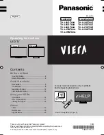
Figure 5-11
START
Connect a pattern generator to the aerial input.
Set Patt.gen. to 475,25 MHz, colourbar, stereosound, PAL B/G (for France SECAM L).
Put Mainsswitch : on
In normal conditions the set will start with the sequence :
red LED.., orange LED..,green LED.
Then after few seconds sound and picture will appear
Does the red LED
light
?
Yes
Read Error
buffer with
Dealer Service Tool
(DST)
Yes
Are there Errors
indicated ?
See Table with
error messages in
chapter 5 of this manual,
which device is causing
the error. Make a note of
the error messages.
Hereafter reset the error
buffer.
No
A
No
(A1);
+5VSTANDBY
on <P4>
OK ?
Yes
(K7);
RESET pulse
on <C1>
OK ?
(K7);
6MHz on
<C3> OK
?
Yes
(K7);
Anode of
D6037
0 V ?
Yes
Check/Replace
(K7);
D6073
TS7012
R3059
(E);
LED6051
Yes
Check/Replace
(K7);
IC7003
Check/Replace
(K7);
X1001
(A1);
<P1>
OK ?
No
Check/Replace
Mains input circuit:
Mains switch,
Fuse 1052
Yes
Repair STANDBY
Supply with:
STANDBY supply
repair kit
4822 310 11235
If the STANDBY Supply
is OK now, but the set is
still not functioning
properly, then switch off
the mains and start all
over again
No
No
No
No
If the LED goes on
with the startup
sequence orange..green
then the set may seem
OK, however there are
also errors, which do not
result in a protection
state. At this point it is
adviceable to read out
the error buffer via the
DST to determine how
to continue with the
faultfinding.
So, read out the error
buffer with the DST
A
Note 2:
(K1)
means Drawing K1
<F11> means Test point F11
MG21FFT1.VSD
Check/Replace
(K7)
TS7006,TS7007,
TS7016
Note
: If reset remains
low, then the set can
function normally.
If reset remains high,
then the set will not
function
1
1
7
3
1
1
7
2
1
1
7
0
1
1
1
A
1
1
1
1
1
1
1
A
Note 1:
IRIS SYMPTOM CODE
1
1
1
A
Condition
code
Main symptom
code
Extended symptom
code
1
3
1
2
Does the LED
remain red
?
Yes
No