Circuit Descriptions, Abbreviation List, and IC Data Sheets
EN 91
LC4.9U AA
9.
9.7.1
Teletext Path
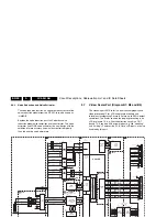
In Pixel Plus and Digital Crystal Clear models, which have an
ADC (B18) and Columbus 3D combfilter (B19), the digital input
of the scaler is used for the digital video signal (Columbus
output), whereas the analogue RGB input of the scaler is used
for teletext. This means that no mixed mode (video plus teletext
simultaneously) is possible. In Crystal Clear models, which do
not have an ADC and Columbus, the analogue RGB input of
scaler is used for both video and teletext (generated by the
Hercules). The digital input of the Scaler is not used in Crystal
Clear TV sets. See also the block diagrams at the beginning of
this chapter. When fault finding, checking the teletext path may
be useful: if there is sound and teletext, but no video and user
menu (blank screen), the digital path (Hercules - ADC -
Columbus - Scaler) is faulty. If there is sound but no teletext,
the back-end part (Scaler - LCD panel) is faulty.
9.7.2
Features
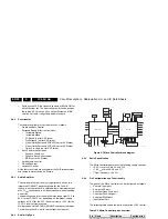
The Scaler provides several key IC functions:
•
Scaling.
•
Auto-configuration/ Auto-Detection.
•
Various Input Ports:
–
Analog RGB.
–
Video Graphics.
•
Integrated LVDS Transmitter.
•
On-chip Micro-controller
9.7.3
Inputs
Analog RGB
The RGB input is fed to pins B2, C2 and D2 of the Scaler IC
(Genesis GM1501, item 7801, see circuit diagram B8). This
input consists of either the Hercules RGB output or the RGB/
YpbPr input of the VGA connector. The Scaler can switch
between the two signals via the PC_HD_SEL signal and
selection IC SM5301 (see circuit diagram B13).
PC (VGA) Input
The VGA input is processed by the VGA block of the Scaler.
The Scaler supports pixel frequencies up to 165MHz.
YpbPr format is also supported via the VGA interface and
covers a resolution of 480p/560p/720p/1080i.
9.7.4
Output
The Display Output Port provides data and control signals that
permit the Scaler to connect to a variety of display devices
using a TTL or LVDS interface. The output interface is
configurable for single or dual wide TTL/LVDS in 18, 24 or 30-
bit RGB pixels format. All display data and timing signals are
synchronous with the DCLK output clock. The integrated LVDS
transmitter is programmable to allow the data and control
signals to be mapped into any sequence depending on the
specified receiver format.
9.8
Audio Processing
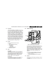
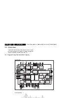
Figure 9-6 Block diagram audio processing
The audio decoding is done entirely via the Hercules. The IF
output from the Tuner is fed directly to either the Video-IF or the
Sound-IF input depending on the type of concept chosen.
There are mainly two types of decoder in the Hercules, an
analogue decoder that decodes only Mono, regardless of any
standards, and a digital decoder (or DEMDEC) that can decode
both Mono as well as Stereo, again regardless of any
standards.
In this chassis, the analogue decoder is used in two cases:
•
It is used for AM Sound demodulation in the Europe
SECAM LL’ transmission.
•
It is used for all FM demodulation in AV-Stereo sets.
9.8.1
Diversity
The diversity for the Audio decoding can be broken up into two
main concepts:
•
The Quasi Split Sound concept used in Europe and some
AP sets.
•
The Inter Carrier concept, used in NAFTA and LATAM.
The UOC-III family makes no difference anymore between
QSS- and Intercarrier IF, nearly all types are software-
switchable between the two SAW-filter constructions.
Simple data settings are required for the set to determine
whether it is using the Inter Carrier or the QSS concept. These
settings are done via the “QSS” and “FMI” bit found in SAM
mode. Due to the diversity involved, the data for the 2 bits are
placed in the NVM location and it is required to write once
during start-up.
On top of that, it can be further broken down into various
systems depending on the region. The systems or region
chosen, will in turn affect the type of sound standard that is/are
allowed to be decoded.
•
For the case of Europe, the standard consists of BG/DK/I/
LL’ for a Multi-System set. There are also versions of
Eastern Europe and Western Europe set and the standard
for decoding will be BG/DK and I/DK respectively. FM
Radio (not applicable for the models discussed in this
manual) is a feature diversity for some Europe TV sets.
The same version can have either FM Radio or not,
independent of the system (e.g. sets with BG/DK/I/LL’ can
have or not have FM radio).
•
For the case of NAFTA and LATAM, there is only one
transmission standard, which is the M standard. The
diversity then will be based on whether it has a dBx noise
reduction or a Non-dBx (no dBx noise reduction).
Side in
*
All region
SCART1 out
*
Europe only
SCART2 out
*Europe only
Monitor out
* Not available
SCART2 in
*Europe only
AV2 in
*
AP/USA/Latam
AV1 in
*
AP/USA/Latam
SCART1 in
*Europe only
Lip Sync
Circuit
2x
Amplifier
Amplifier
PC in
HDMI
DAC
HEF4053
3X SPDT
PC_HDMI_AUD_SEL
(From Scaler,
GPIO_G07_B0)
AUDIO-OUTSL
AUDIO-OUTSR
AUDIO-OUTHPL
AUDIO-OUTHPR
Constant Level Out
*
Europe only
AUDIO-LSL
AUDIO-LSR
Tuner
SIF
Is used on the DMMI
=> No SCART2/AV2 for
Bolt-on
AUDIO-IN5L
AUDIO-IN5R
AUDIO-IN3L
AUDIO-IN3R
AUDIOI-N4L
AUDIO-IN4R
AUDIO-IN2L
AUDIO-IN2R
SIF Input
106
105
103
P0.0/I2SDI1
P0.0/I2SDO1
P0.3/I2SCLK
I2S
FM
SSIF Input
2x Stereo
Speaker
Headphone
Hercules
For iTV only
E_14490_061.eps
121104

