Mechanical Instructions
EN 9
LC4.9U AA
4.
4.3.3
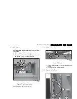
Side I/O Panel
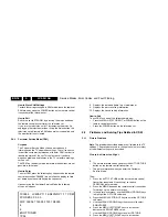
After removal of the Speaker Compartment Covers, this panel
is accessible.
1.
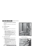
Disconnect the cable (1) from the panel.
2.
Remove the T10 mounting screws [2] that hold the assy.
3.
Remove the panel from its bracket [3], by pushing against
the front side of the side I/O cinch connectors.
Figure 4-7 Side I/O panel removal
When it is defective, replace the whole unit.
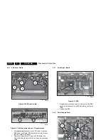
4.3.4
LED Panel
Figure 4-8 LED panel
1.
Remove the fixation screws (1) and take the panel out of its
brackets.
2.
Disconnect the cable (2) from the panel.
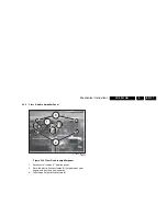
4.3.5
Keyboard Control Panel
Figure 4-9 Keyboard control panel
1.
Remove the panel (1) from its three brackets (2).
2.
Disconnect the cable (3) from the panel.
F_15430_048.eps
100605
2
1
3
F_15420_036.eps
070605
1
2
F_15420_037.eps
070605
2
1
3


